I recently pushed the limits of .308 Winchester using Alpha Munitions OCD brass. Details of the brass, reloading process, and the rifle’s chamber all have to come together perfectly for safe, proper firing. Here’s how it works! Disclaimer Ultimate Reloader LLC / Making with Metal Disclaimer: (by reading this article and/or watching video content you […]
Category: Reloading Safety

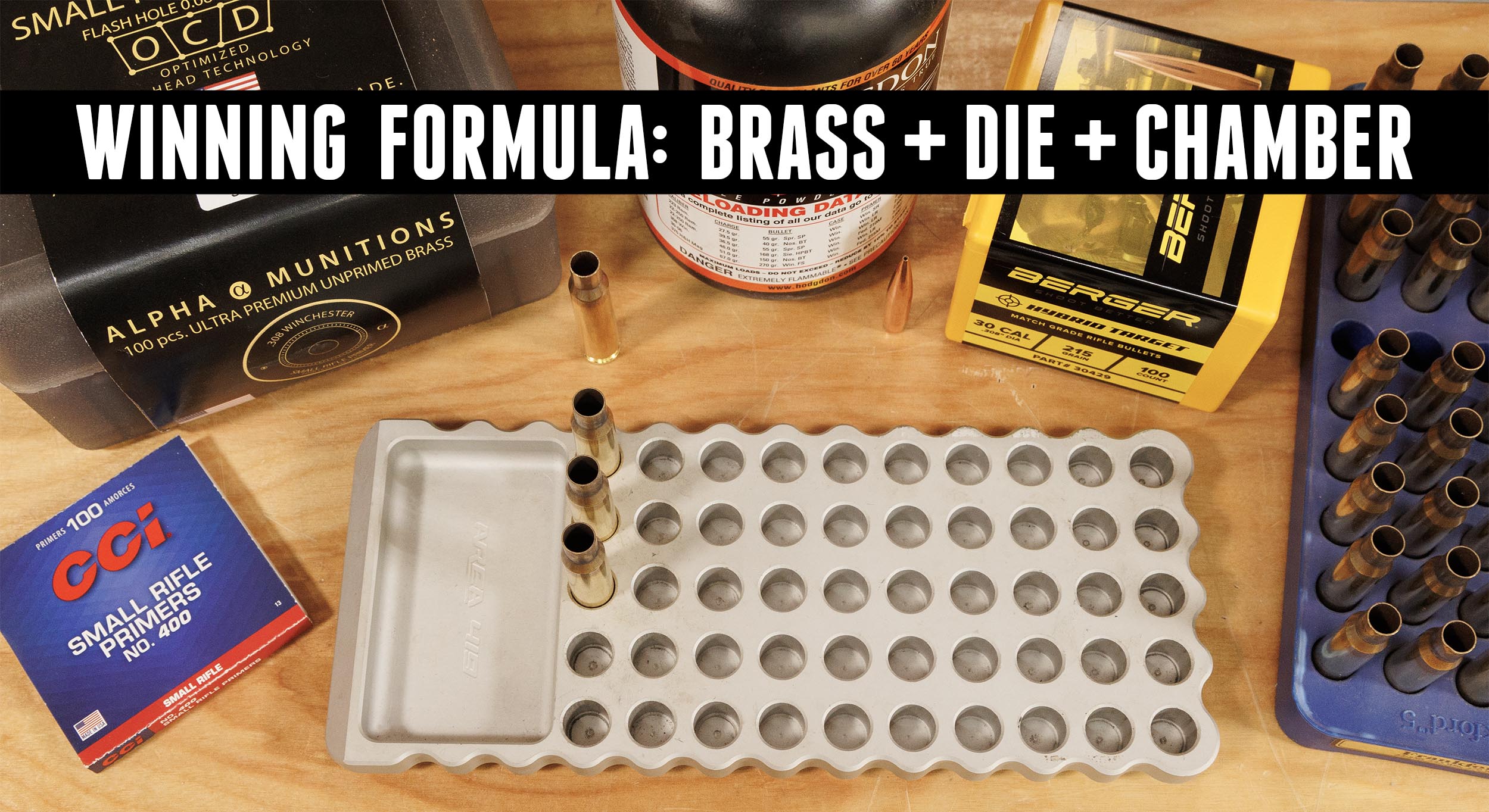
INSANE Performance: Pushing the 308 Win into 300 Win Mag Territory (Bat Machine, Alpha Munitions)
DO NOT TRY THIS AT HOME. I’ve joined forces with BAT Machine and Alpha Munitions to truly test how hard we can push a .308 Winchester. Disclaimer Ultimate Reloader LLC / Making with Metal Disclaimer: (by reading this article and/or watching video content you accept these terms). The content on this website (including videos, articles, […]
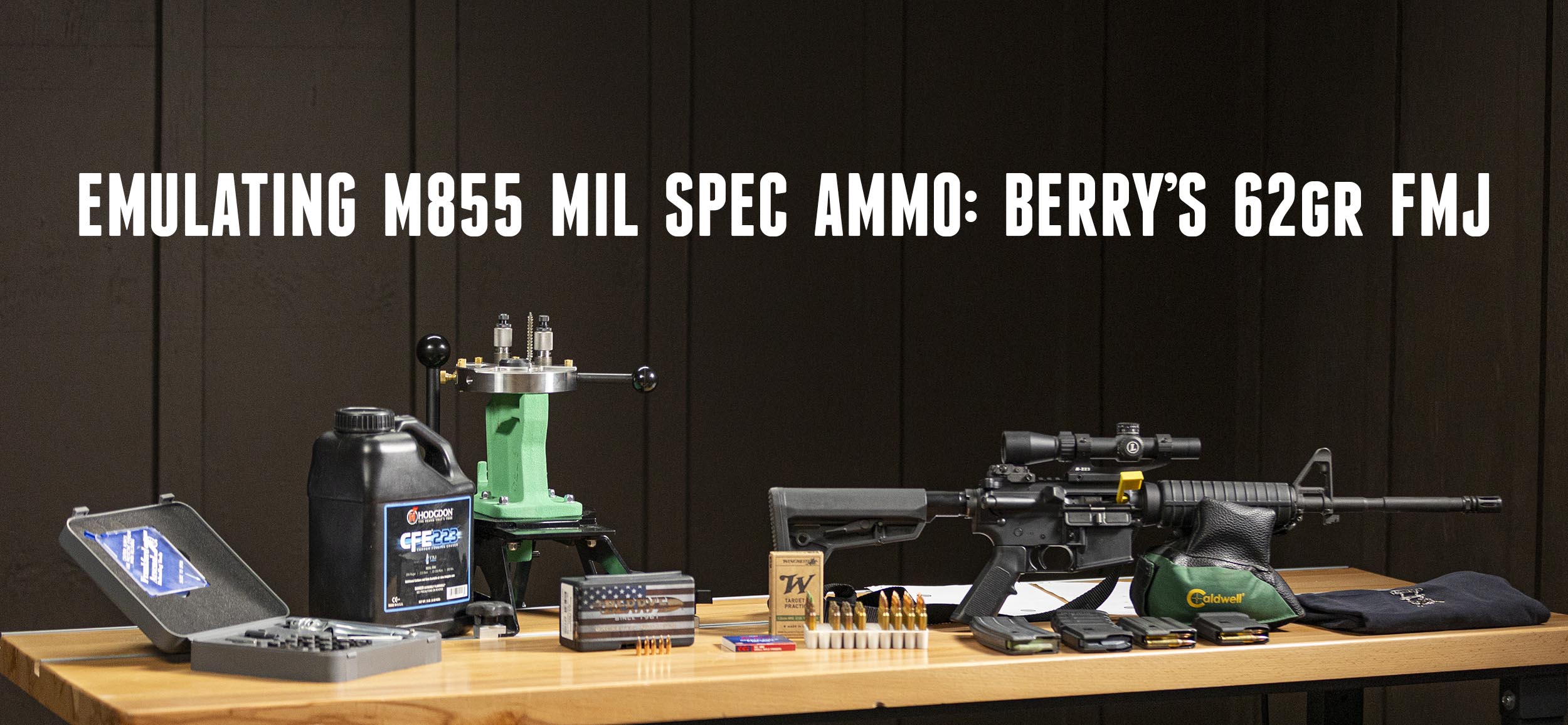
Economical .223 Loads: Berry’s 62 grain FMJ
I’ve spent many many hours with the AR-15 through decades of military and law enforcement experience. Disclaimer Ultimate Reloader LLC / Making with Metal Disclaimer: (by reading this article and/or watching video content you accept these terms). The content on this website (including videos, articles, ammunition reloading data, technical articles, gunsmithing and other information) is […]
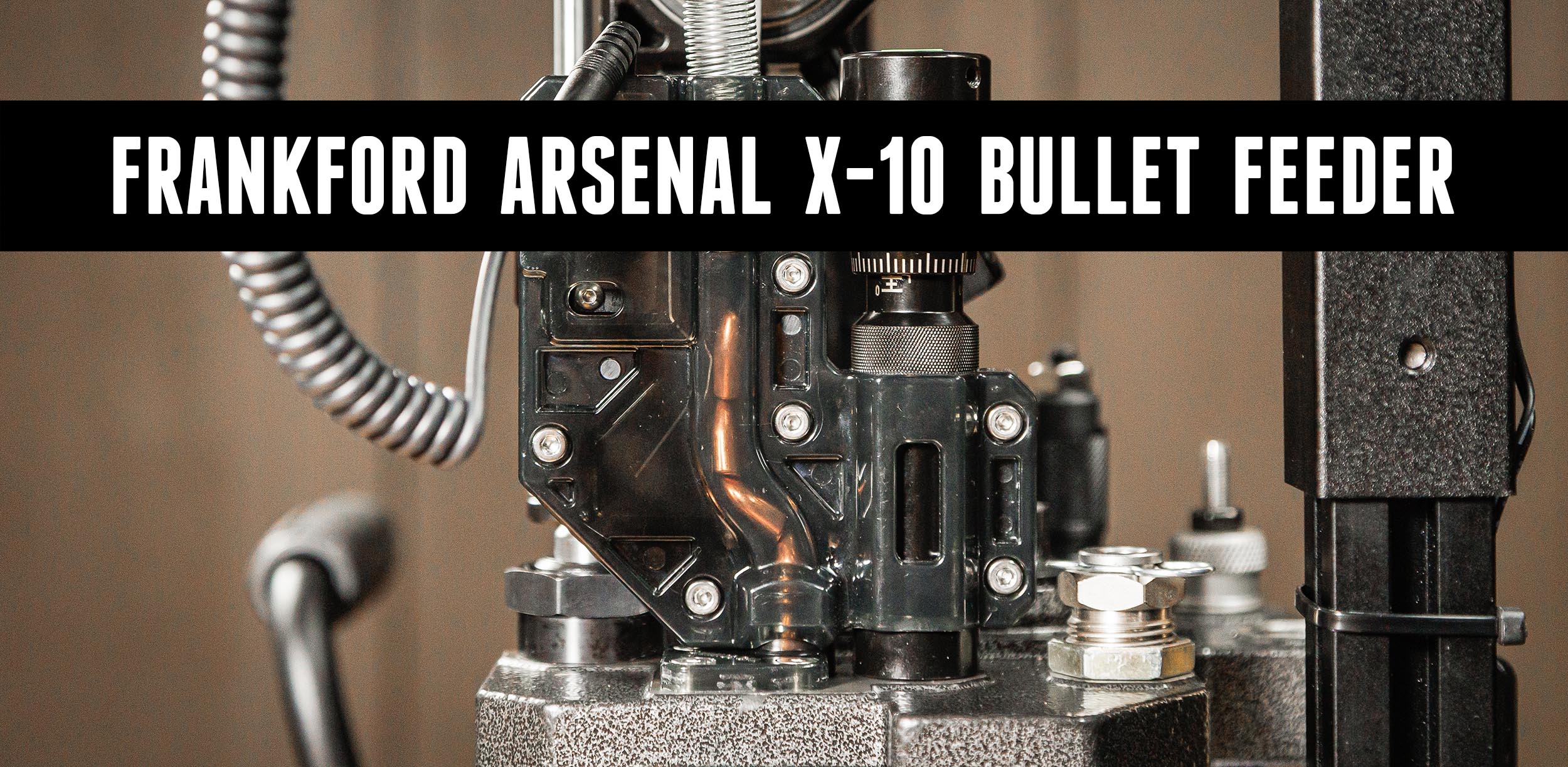
Frankford Arsenal X-10 Bullet Feeder: Unboxing, Setup, Loading 9mm
While I’ve done several stories with the Frankford Arsenal X-10 Progressive Press, I decided it was time for Ultimate Reloader’s Kyle Shields to set up the production version, and to add the new bullet feeder! Disclaimer Ultimate Reloader LLC / Making with Metal Disclaimer: (by reading this article and/or watching video content you accept these […]

LEE Six Pack Pro: KMS² UFO Press Light and Inline Fabrication Mount
KMS² just released their UFO SP press light for the LEE Six Pack Pro. Midsouth Shooters Supply sent along a LEE Six Pack Pro for me to work with and Inline Fabrication sent a No. 95 quick change top plate for their Ultramount system. Disclaimer Ultimate Reloader LLC / Making with Metal Disclaimer: […]
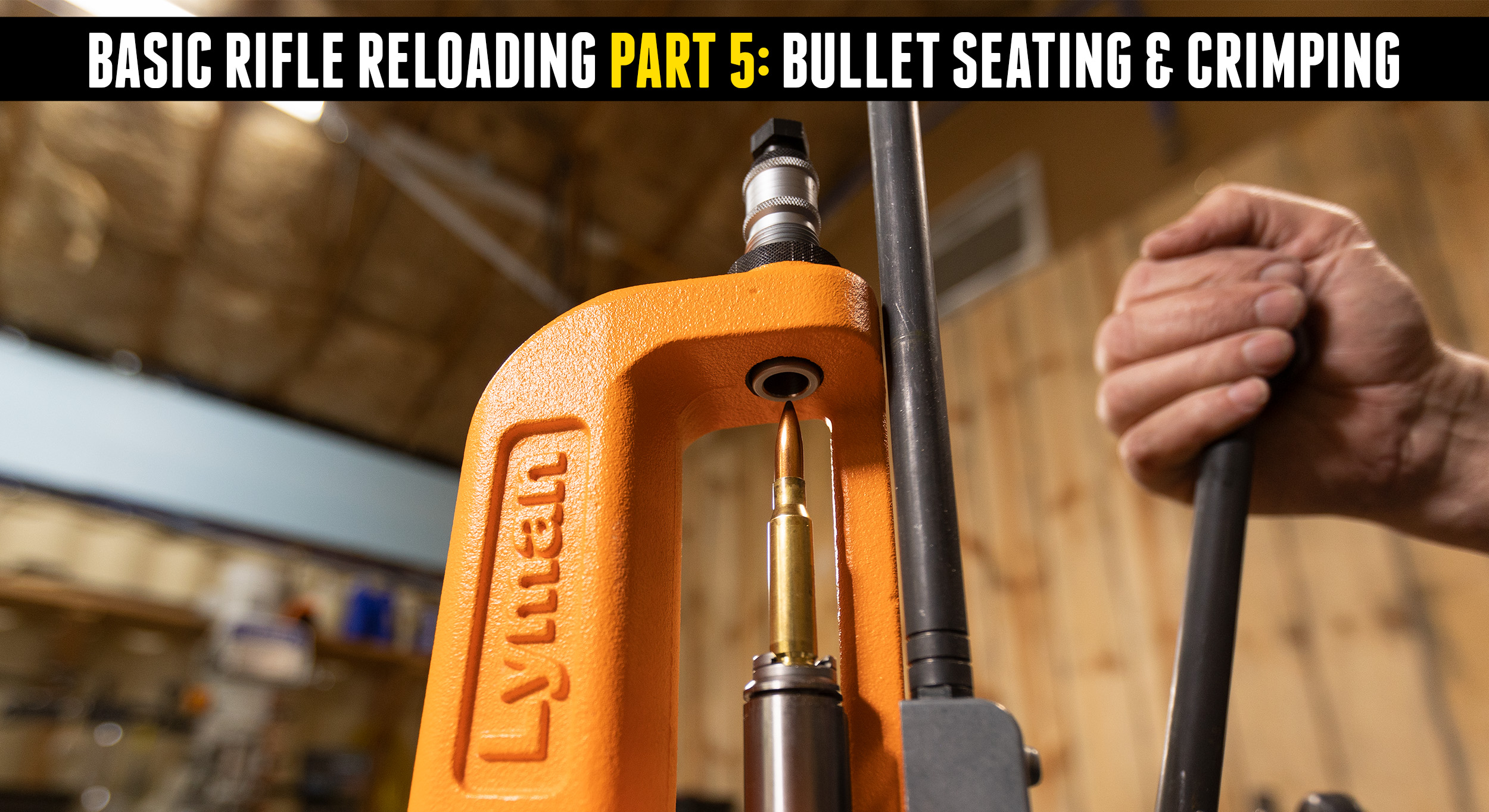
Basic Rifle Reloading 5: Bullet Seating & Crimping
At this point we have cleaned and lubed the brass, resized it, primed it and dropped in the powder charge. It’s time to seat the bullet! Disclaimer Ultimate Reloader LLC / Making with Metal Disclaimer: (by reading this article and/or watching video content you accept these terms). The content on this website (including videos, articles, […]
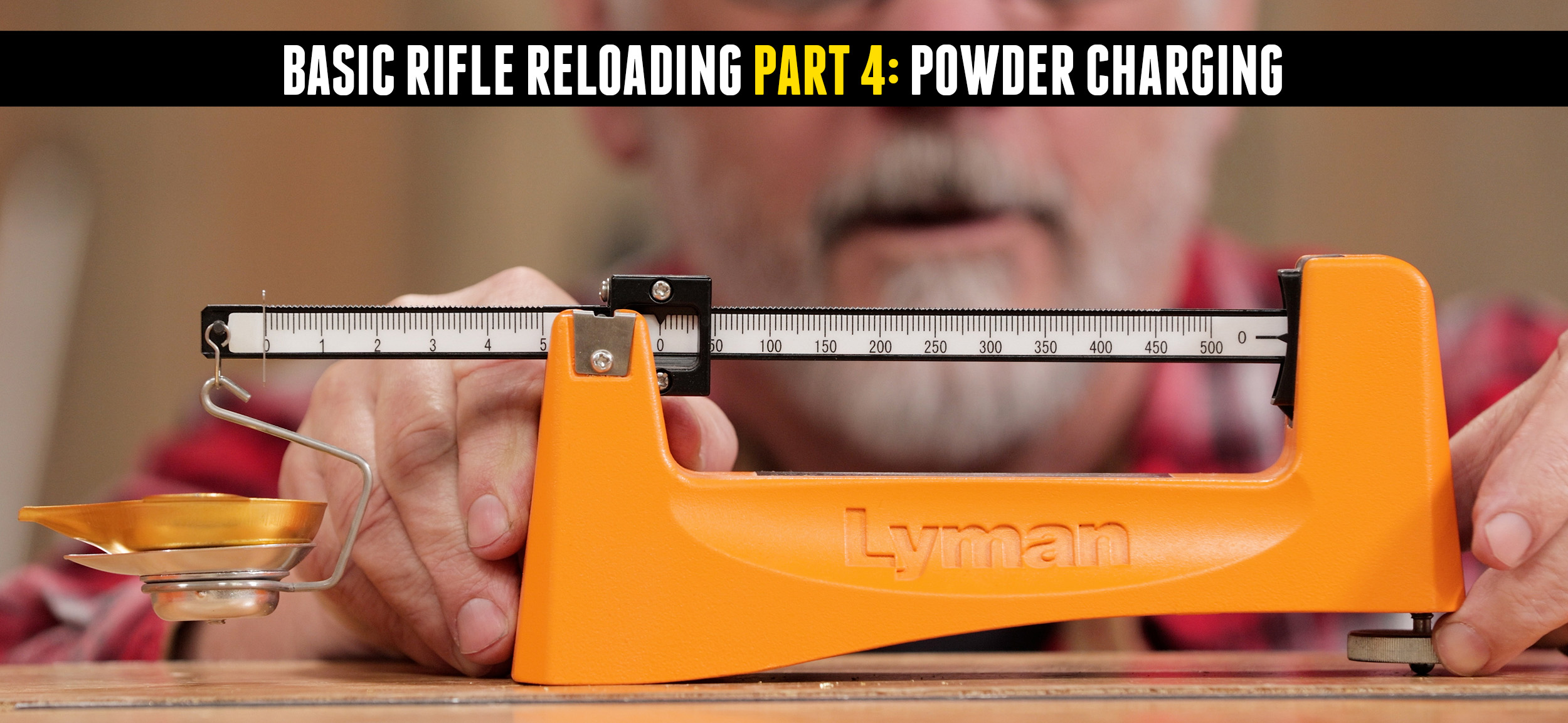
Basic Rifle Reloading Part 4: Powder Charging
To this point we’ve cleaned, resized, trimmed, and primed our rifle brass. Now it’s time to charge it with smokeless powder! Disclaimer Ultimate Reloader LLC / Making with Metal Disclaimer: (by reading this article and/or watching video content you accept these terms). The content on this website (including videos, articles, ammunition reloading data, technical articles, […]
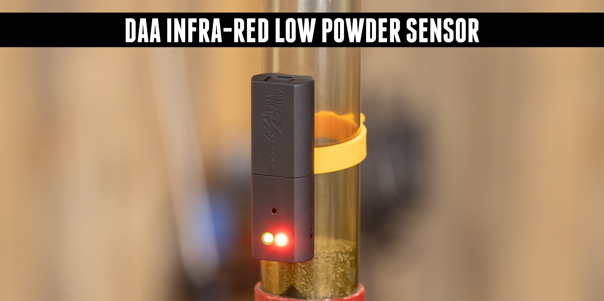
NEW DAA Infra-Red Low Powder Sensor (Hands-On)
Ever run out of powder while loading? The DAA Infra-Red Low Powder Sensor prevents this issue! Disclaimer Ultimate Reloader LLC / Making with Metal Disclaimer: (by reading this article and/or watching video content you accept these terms). The content on this website (including videos, articles, ammunition reloading data, technical articles, gunsmithing and other information) is […]
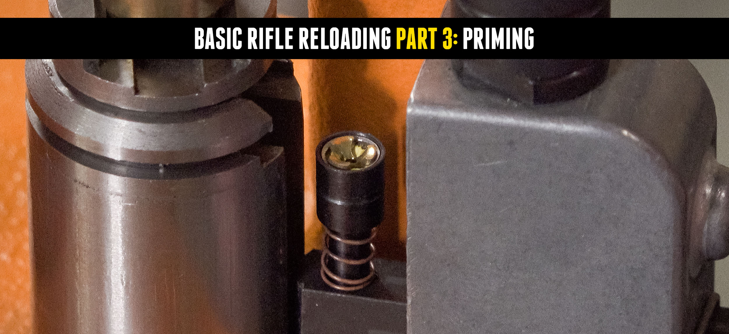
Basic Rifle Reloading Part 3: Priming
In the first video in this series, we cleaned once-fired Federal cases using Lyman’s vibratory tumbler and walnut shell media. We then resized the cases, decapped/deprimed them, trimmed them and did any other necessary case-prep work. Next up is priming! Disclaimer Ultimate Reloader LLC / Making with Metal Disclaimer: (by reading this article and/or watching […]
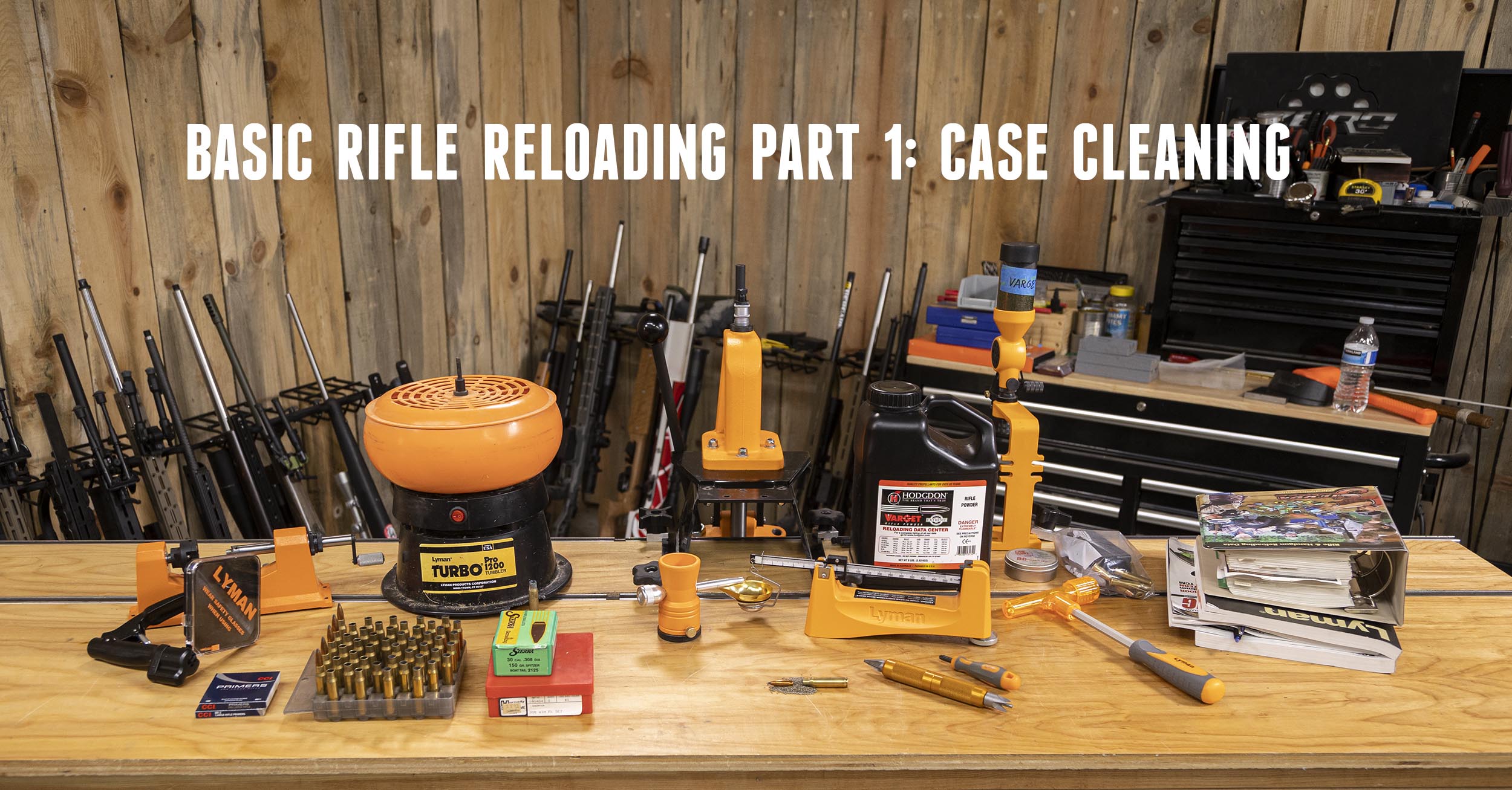
Rifle Reloading Basics Pt1: Safety and Brass Tumbling
Here at Ultimate Reloader, we use a lot of sophisticated equipment, but every person needs to start with the basics. In this series, we’ll review the basics of reloading for all the beginners out there, starting with cleaning brass! Disclaimer Ultimate Reloader LLC / Making with Metal Disclaimer: (by reading this article and/or watching video […]
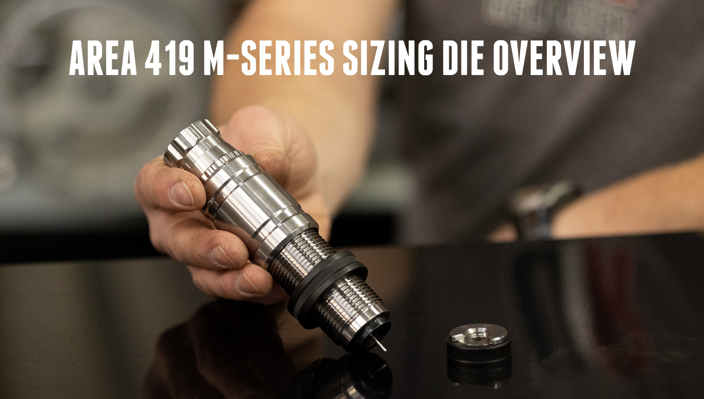
NEW Dies from Area 419: M-Series Sizer (In-Depth)
Brand new dies from AREA 419 and something never seen before! Learn more about them below! Disclaimer Ultimate Reloader LLC / Making with Metal Disclaimer: (by reading this article and/or watching video content you accept these terms). The content on this website (including videos, articles, ammunition reloading data, technical articles, gunsmithing and other information) is […]
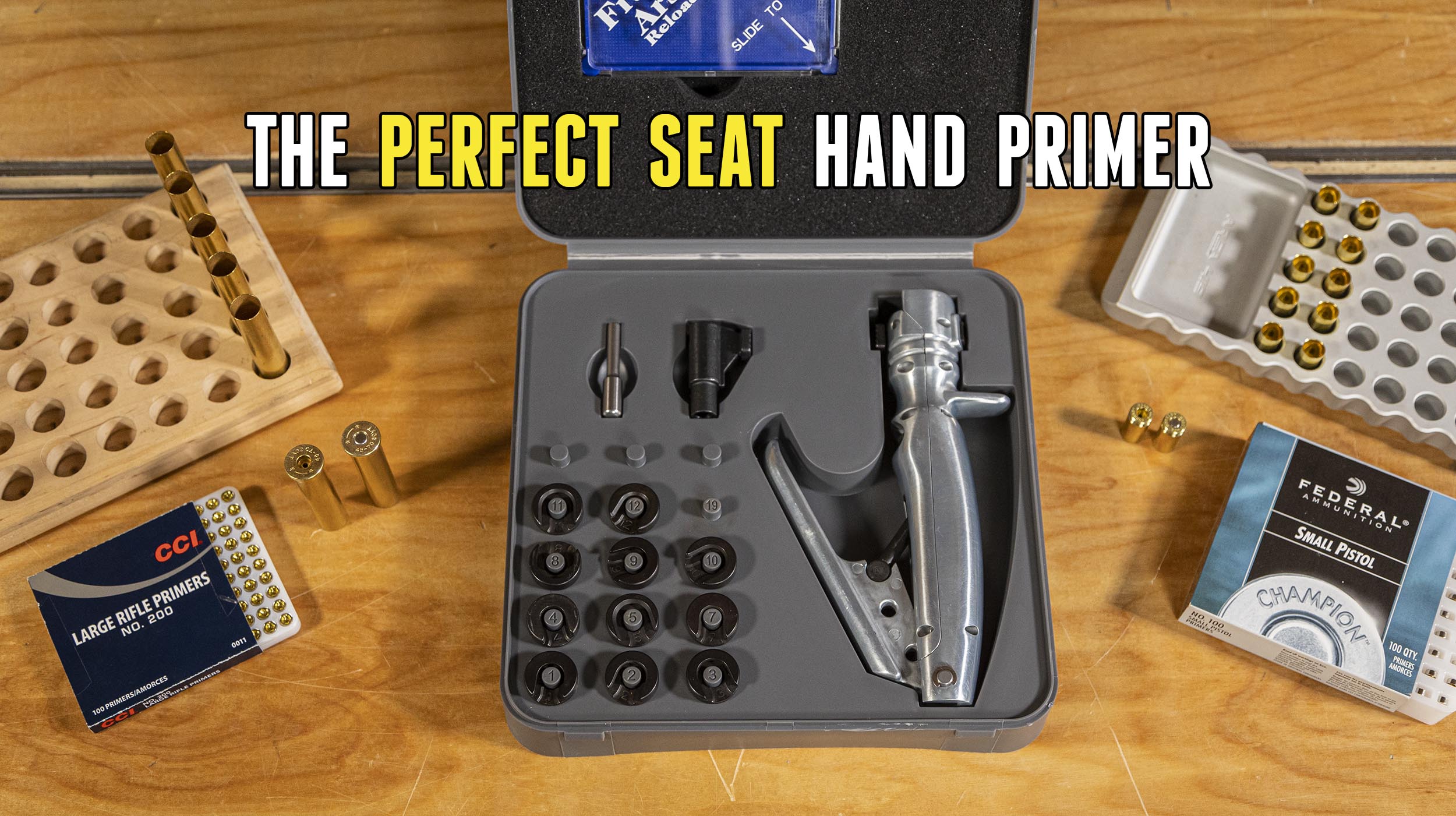
Perfect Primer Seating with Frankford Arsenal
Though priming a large number of cases can be taxing, many prefer handheld priming tools because the handloader can feel the primer being seated into the primer pocket. A properly seated primer is vital for consistency and accuracy. Primer seating on most presses provides so much leverage that “feel” is sacrificed. Some handheld priming tools […]
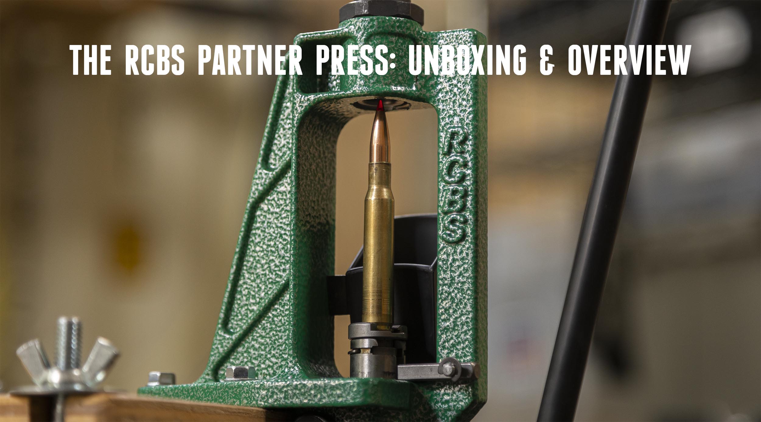
RCBS Lightweight Partner Press Unboxing and Overview
Sometimes less is more. Many presses are large, bulky, and very heavy. However, from time to time, a handloader may want a smaller, lighter press. The RCBS Partner Press is an interesting alternative to large, heavy presses. Disclaimer Ultimate Reloader LLC / Making with Metal Disclaimer: (by reading this article and/or watching video content you […]
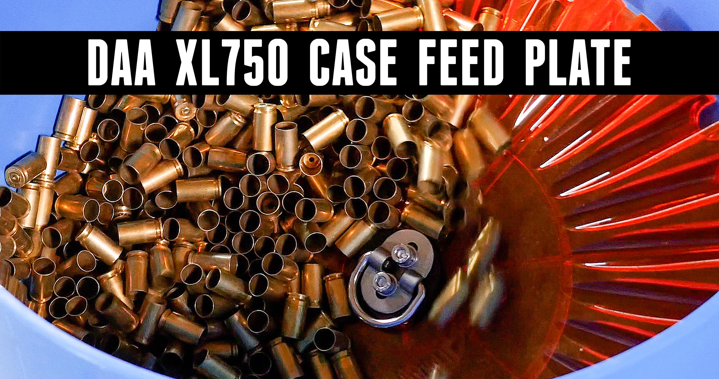
TESTED: Double Alpha Academy Turbo Case Feeder
Does the turbo case feeder plate from Double Alpha Academy expedite your progressive reloading? We put it to the test! Disclaimer Ultimate Reloader LLC / Making with Metal Disclaimer: (by reading this article and/or watching video content you accept these terms). The content on this website (including videos, articles, ammunition reloading data, technical articles, gunsmithing […]
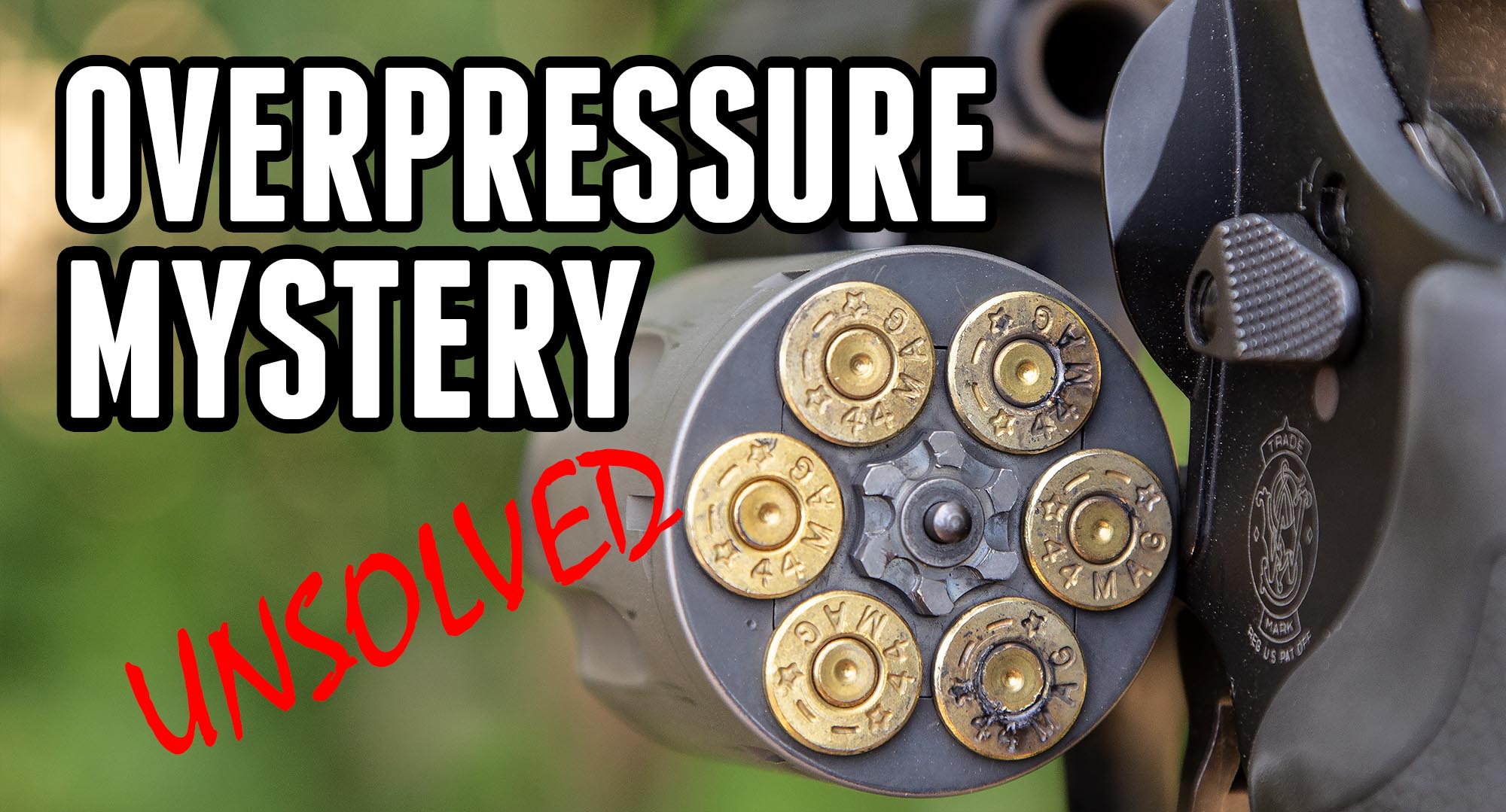
Unsolved: 44 Magnum Over-Pressure Mystery
Ever go about your day doing the same things you’ve done a thousand times before and then WHAM! something unexpected happens? That’s what happened to me recently when I was shooting some 44 Magnum handloads. Having just gotten my S&W 329 PD setup for summer carry, I thought I would test some ammo with it. […]
Reloading Safety: Conclusion and Summary
Well, it’s time to sum up the results of the series on reloading safety here on Ultimate Reloader. We started with a high-level look at reloading safety concepts, and then took a deep-dive into the various products available for validating your powder charge. Here’s a quick set of links for the articles that we’ve covered: […]
RCBS Powder Checker Die
There’s one more powder check system that we’re going to look at on our reloading safety series- the “RCBS Powder Checker Die”. This unit is very simple, easy to setup, and works well. It’s comparable to the “Hornady Powder Cop Die”. This system is quite versatile, and intuitive to setup and use. Let’s take a […]
Hornady Powder Cop Die – Overview
If you’ve been following the “powder check systems” blog series, you may be wondering about how the Hornady Powder Cop die compares with all of the other powder check systems. Well, in this article we’ll take a look at this system, examine its features, and walk through setup with this die. The Hornady powder cop […]
RCBS Lock-Out Die Part II: Setup and Maintenance
In the first RCBS Lock-Out Die article, I discussed how the RCBS Lock-Out Die works. In this article, we’ll take a look at how to setup the die, and also how to disassemble and reassemble the die for cleaning and maintenance. There are multiple ways to skin a cat, and likewise, there are multiple ways […]
RCBS Lock-Out Die Part I: Theory of Operation
Most reloaders have heard of the RCBS Lock-Out Die. This device will allow the reloading press to cycle normally when there is a proper powder charge, but will “lock up” the press if there is too much powder in the charge, or not enough powder in the charge (including no powder – a “squib load”). […]
Dillon XL-650 / 1050 Powder Check System
Recently, I’ve been writing about reloading safety. This is perhaps the most important thing to incorporate into your reloading workflow! In my last post, I gave a high-level view and comparison of the various popular powder check systems that are on the market today. There are really quite a few options that are tailored to […]
Reloading Safety: Powder Check Systems Overview
In my last post, I outlined some basic principles for reloading safety. One of the basic ways that you can ensure your safety while reloading is by using a quality powder check system- especially when loading with a progressive reloading press. So next, I thought it would be a good idea to look at some […]
Reloading Safety – A basic primer
If you are like me, the thought of playing with gunpowder and bullets is inherently interesting. It goes without saying that it is also very dangerous. I personally feel lucky to have all of my fingers, toes, and other appendages intact (thinking back to 4th of July as a kid). I’d be happy to keep […]