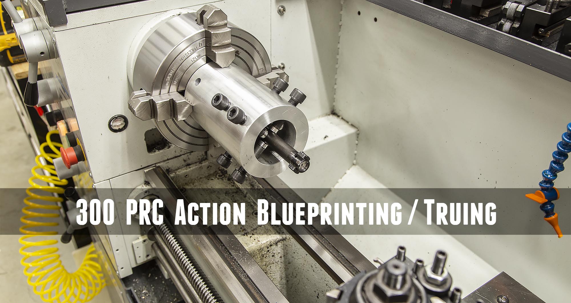
I’m excited to kick off my 300 PRC “Budget Build” in this article. I’ve been working on putting together all of the related pieces and parts, have taken training with Gordy Gritters, and have previously completed a 300 PRC full-custom build, and now it’s time for the 2nd 300 PRC build! In this story I’ll outline the components/tools/parts I’ll be using for the build, and will walk through the action truing/blueprinting job that I just completed for this build.
Starting Point: Remington 700 Long-Range 300 RUM
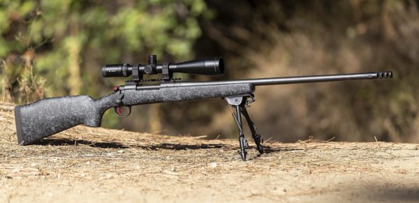
This rifle this build is based off is a Remington 700 Long-Range chambered in 300 Remington Ultra-Magnum. You’ll want to check out the story I published which gives an overview of this rifle. It’s a really nice starting point for a build because of the solid “building blocks” present in the Remington 700 Long-Range package including:
- Bell and Carlson fiberglass stock with aluminum inletting and pillars
- Remington 700 long-action receiver- the “industry standard” for rifle builds
With a rifle like this, the only limits are your imagination!
Disclaimer
Ultimate Reloader LLC / Making with Metal Disclaimer: (by reading this article and/or watching video content you accept these terms)
- The content on this website (including videos, articles, ammunition reloading data, technical articles, gunsmithing and other information) is for demonstration purposes only.
- Do not attempt any of the processes or procedures shown or described on this website.
- All gunsmithing procedures should be carried out by a qualified and licensed gunsmith at their own risk.
- Do not attempt to repair or modify any firearms based on information on this website
- Ultimate Reloader, LLC and Making With Metal can not be held liable for property or personal damage due to viewers/readers of this website performing activities, procedures, techniques, or practices described in whole or part on this website.
- By accepting these terms, you agree that you alone are solely responsible for your own safety and property as it pertains to activities, procedures, techniques, or practices described in whole or part on this website.
Taking Inventory for the Build
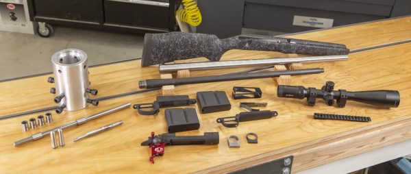
Before we get into the action blueprinting, let’s take a look at the parts and pieces as well as tooling for the build, from left to right in the above image we have:
Gre-Tan Tools (left-hand side, from top to bottom):
- Gre-Tan Rifles Action Blueprinting Jig
- Gre-Tan Rifles 1/2″ x 14″ Indicating Rod
- Gre-Tan Rifles Bushing Set for Remington 700 Actions
From Dave Manson Precision Reamers:
- 300 PRC Piloted Finisher Reamer
- 30 caliber bushing set (not pictured)
- 300 PRC Go Gauge
- 300 PRC No-Go Gauge
Rifle Parts (right-hand side, from top to bottom):
- Bell and Carlson M40 style Fiberglass Stock
- Benchmark Barrels 26″ finished length 8.5:1 twist MTU profile barrel blank
- 300 RUM factory take-off barrel (which I threaded the muzzle on)
- Accurate Mag long-action bottom metal
- Accurate Mag 300 PRC-length magazines
- Factory bottom metal with hinged floorplate
- Internal magazine
- Vortex Viper HS-T 6-24x50mm scope and rings
- EGW Remington 700 Long Action 20 MOA Scope Rail
- Trued Remington 700 Long-Action receiver, bolt + Elftmann Tactical ELF 700 SE Trigger
- Badger Ordnance 0.312″ thick tapered recoil lug
With this tooling and gear, the stage is set for an awesome build!
My Lathe
For this build, I’m using a Precision Matthews PM-1440GT. I believe this is the best gunsmithing lathe you can by new in the USA (Taiwanese made, not chinese, 2″ through-spindle capacity, Japanese high-precision spindle bearings, etc):
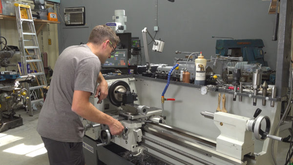
Also, I’ll be using the custom outboard spider that I built- you’ll want to check out that story!
Considerations for Action Blueprinting
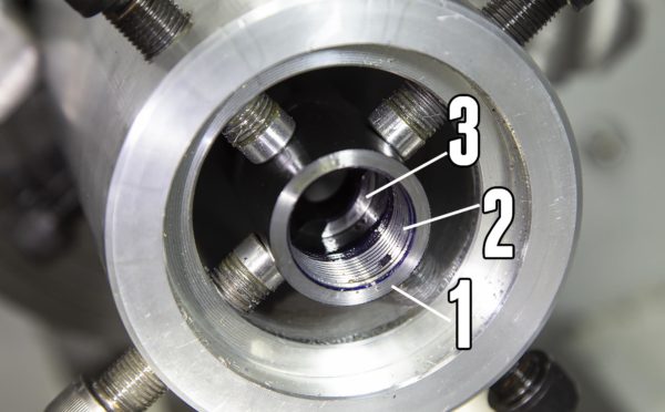
There are a few things that are super-important when truing-up an action, starting with the receiver (see above image of trued receiver):
- Squareness and flatness of receiver face (should have near zero runout when indicated)
- Receiver threads should have minimal runout (run concentric)
- Lug seats should be uniform and at the same depth
And with the bolt:
- Bolt lug faces should be uniform and at same depth
- Bolt face should not have runout
- Bolt lugs and lug seats should contact each other evenly when the trigger is installed and cocked, rifle ready to fire
Next, we’ll walk through the steps required to achieve the above goals/requirements.
Truing the Receiver
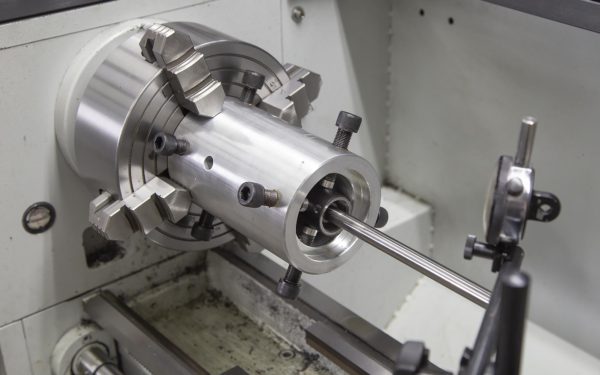
The starting point for truing the receiver is to install the truing jig in the lathe, and to get the receiver mounted and aligned. Here’s the process I went through:
- Install alignment bushings in receiver
- Install GreTan action blueprinting jig in lathe
- Install receiver in blueprinting jig
- Install alignment rod in bushings/receiver
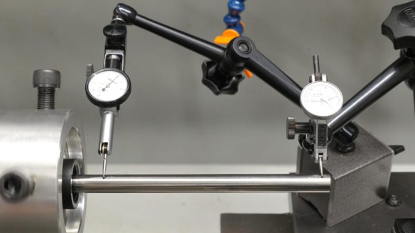
- Use 0.001″ indicator to do rough alignment
- Use two 0.0001″ indicators to perform final alignment
- Remove alignment rod and outboard bushing from receiver (the inboard bushing will be removed after we remove the receiver from the fixture)
At this point, the receiver is running true to the lathe spindle. It’s important to note that the “datum” or “reference” here is the receiver bore we fit the bushings into.
Next, it’s time to take some measurements. I used a 0.0001″ indiactor to measure the following:
- Thread concentricity (measuring critical side of threads, the ones pointing towards the inside of the receiver)
- Receiver face runout
- Lug seat depth and runout
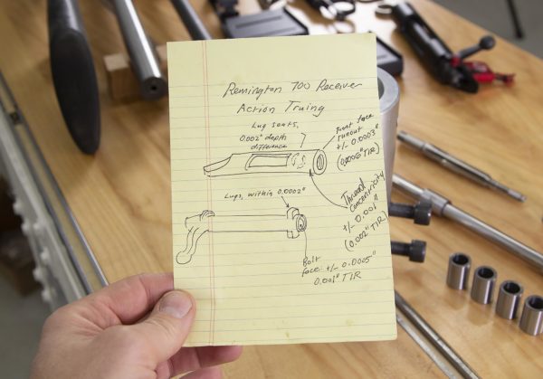
Here’s my evaluation sheet from these measurements:
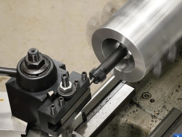
I started with truing up the receiver threads. I spent most of my time working on techniques for observing tool position which is difficult in the interior of the receiver!
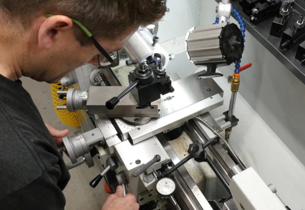
In the above picture you can see my setup:
- Compound set to the left at 29°
- DRO set to 0.0000″ on Z (left-right) where threading passes stop (not in picture)
- Dial indicator set to “0” where threading passes stop
- Lathe setup for 16 TPI threading (receiver threads checked with thread pitch gauge)
The reason for the dial indicator is to know when to withdraw the tool from the thread (using the cross slide). The DRO is used to confirm after the tool is withdrawn. The threads were cleaned up on the critical (inward facing side) first, then the non critical side of the thread was cleaned up (the ones you can see looking into receiver).
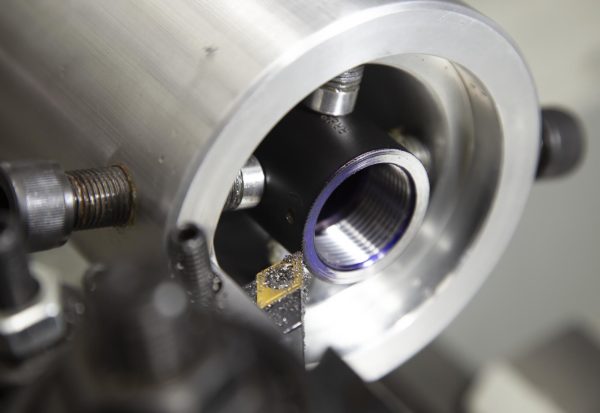
Next I trued up the receiver face with a couple light passes. I used a conventional tool and a boring bar here. The boring bar ended up giving the best surface finish. Here you can see the first pass which cut about 1/2 the way around:
Finally, the lug seats were cut to the same depth using a boring bar, taking off only as much material as was needed (just over 0.002″):
The receiver is now trued. On to the bolt!
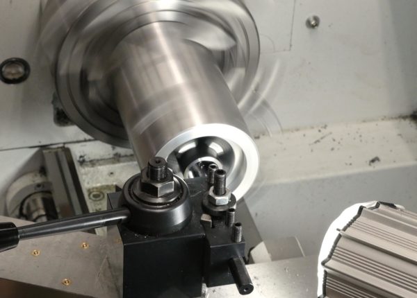
Truing the Bolt
You can use the Gre-Tan action blueprinting jig for working on bolts (with handle installed), but you’ll need to mill a slot on one side for the bolt handle to protrude- not a difficult task! Once the bolt is indicated to run true along its body, the following areas are examined:
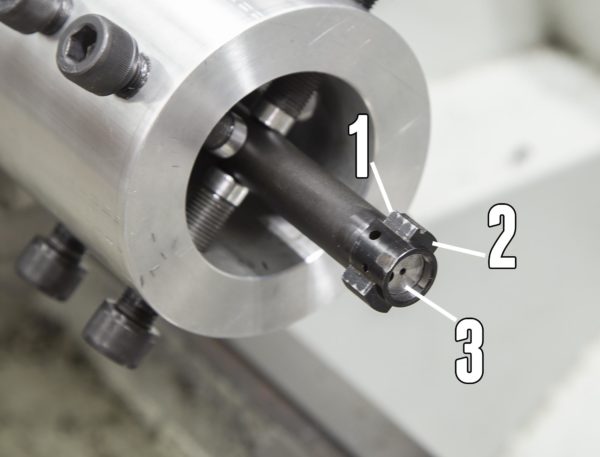
- Bolt lug faces (critical side)
- Bolt lug faces (non-critical side, optional cosmetic clean-up)
- Bolt face
You can also evaluate sleeving the bolt for tighter tolerances in the bore of the receiver. I did not look at that for this build. Since the critical side of the bolt lugs were running pretty true (+/- 0.0001″) I opted to lap them rather than cut them. I could have cleaned them up on the lathe, but lapping works just as well for this minor runout.
So I focused on the bolt face which had a total runout of 0.001″. A couple light passes cleaned it right up: (see picture above for finished product)
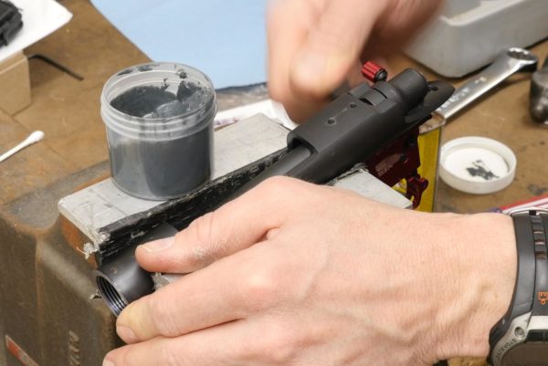
Lapping the Lugs
The final step for my action blueprinting job was to lap the lugs and lug seats together with some 400 grit lapping compound. If you do this with the trigger installed and cocked, you’ll seat these critical mating surfaces to perfect contact when the rifle is ready to fire- the condition that’s most important when you think about the lugs and seats. It took only a couple passes of lapping to bring these surfaces into perfect specifications:
What’s Next
You’ll want to check out the second installment for this build where I’ll be chambering the barrel, threading the muzzle, and putting the rifle together. Make sure you’re subscribed!
Thanks,
Gavin


I’m new to your page. who is Gordy that you’re talking about? I don’t know who the top gunsmiths are, you mentioned that he offers a class. I would be interested in this could you send me some information about him. I’ve been a machinist for over 40 yrs. so that’s the easy part for me, it’s learning the various designs of rifles and how to improve them that’s the challenge for me. I heard you mention your grandfather’s tools in this video, my advise to you is to study basic cutter geometry by looking at HSS end mills and various cutters and your grandfathers cutters. You will be surprised what you can grind up by hand with some practice. You can’t always buy what you need when you’re doing custom work so you just make it. Good luck and thank you. Bill