Originally published on our sister site Making with Metal.
One of the first things I do when I get a new piece of machine shop equipment is to decide how I’ll “customize” the machine and organize all of the tooling. Machining is a very personal thing, and it’s therefore “just a part of the process” to get things dialed-in and setup the way the operator wants them. For a gunsmithing lathe, an “outboard spider” is an absolute must, and that’s the topic of this article!
Why You Need a Lathe Spider
And outboard spider is required when you want to:
- Dial in rifle barrels through the spindle (precise alignment and work holding/support)
- Support long material that may “whip” due to being slender
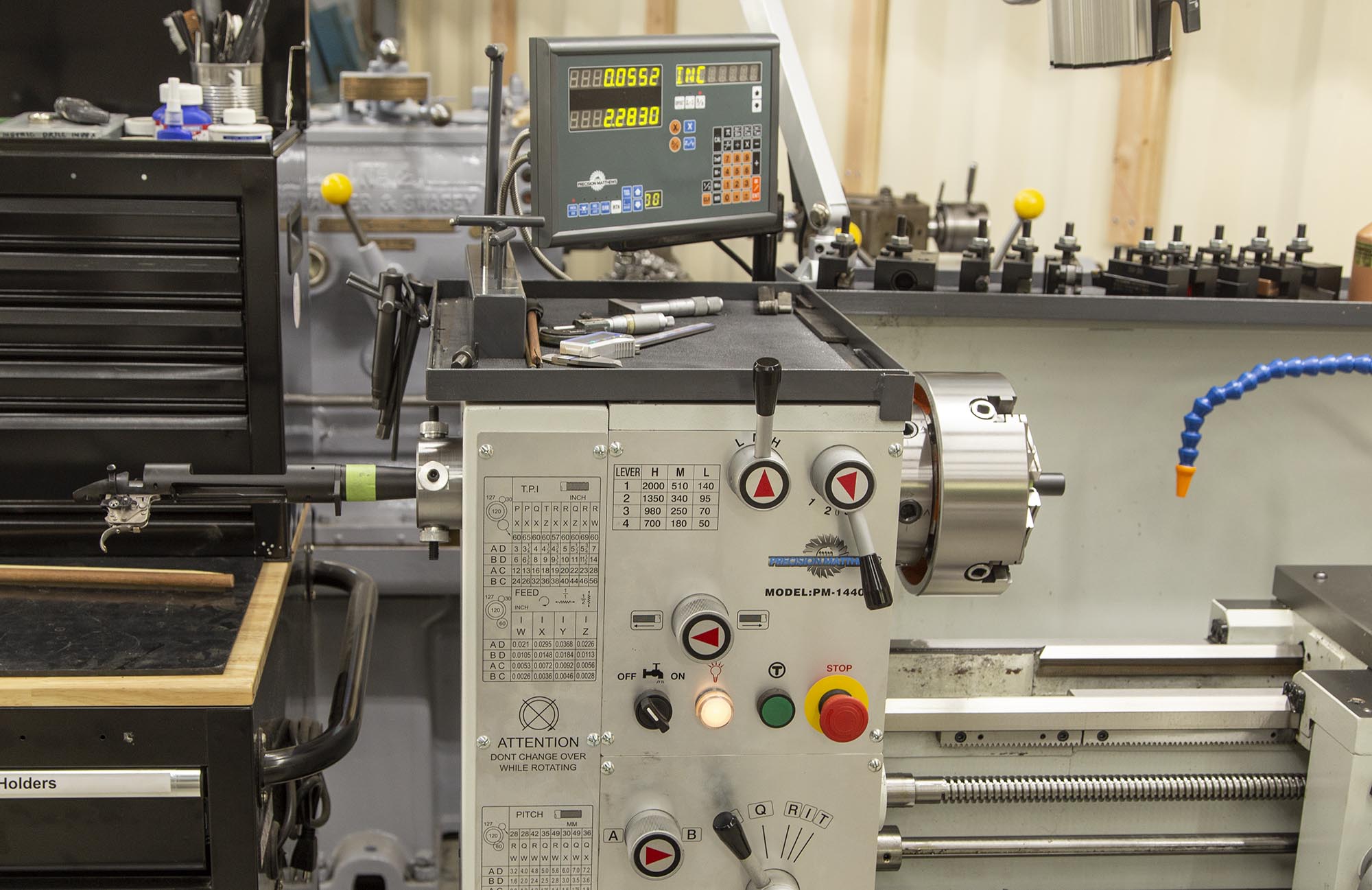
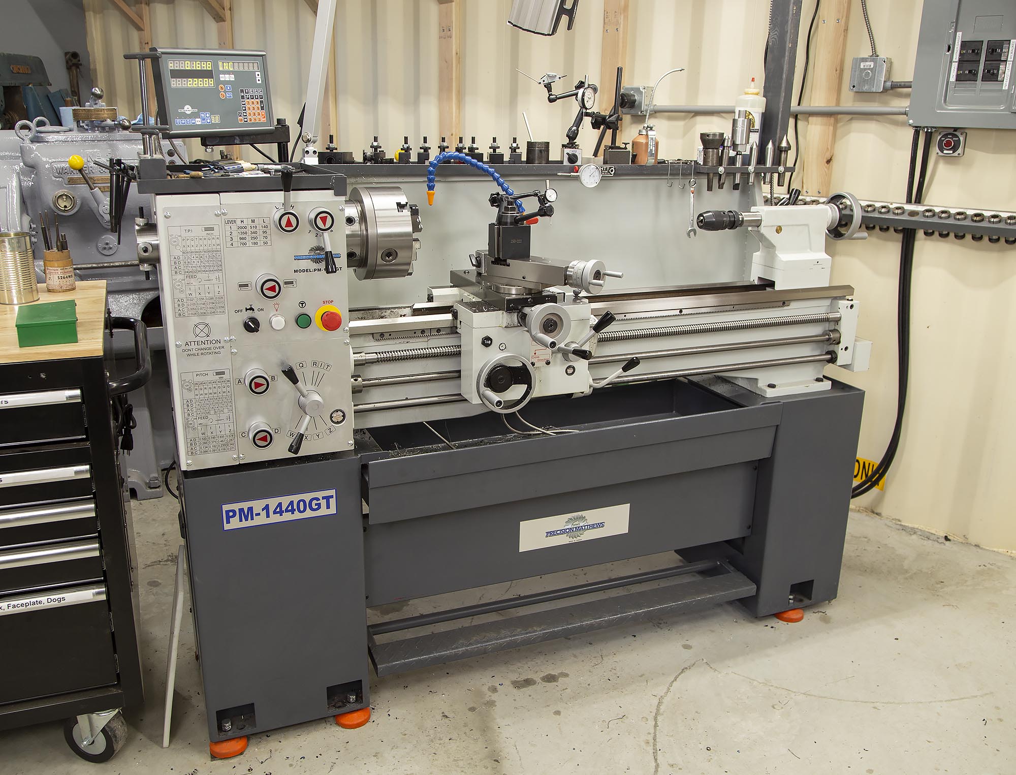
Some lathes come with spiders installed, but not the Precision Matthews PM-1440GT, so when I got mine I had a project on my hands!
Starting Point: DOM Tubing
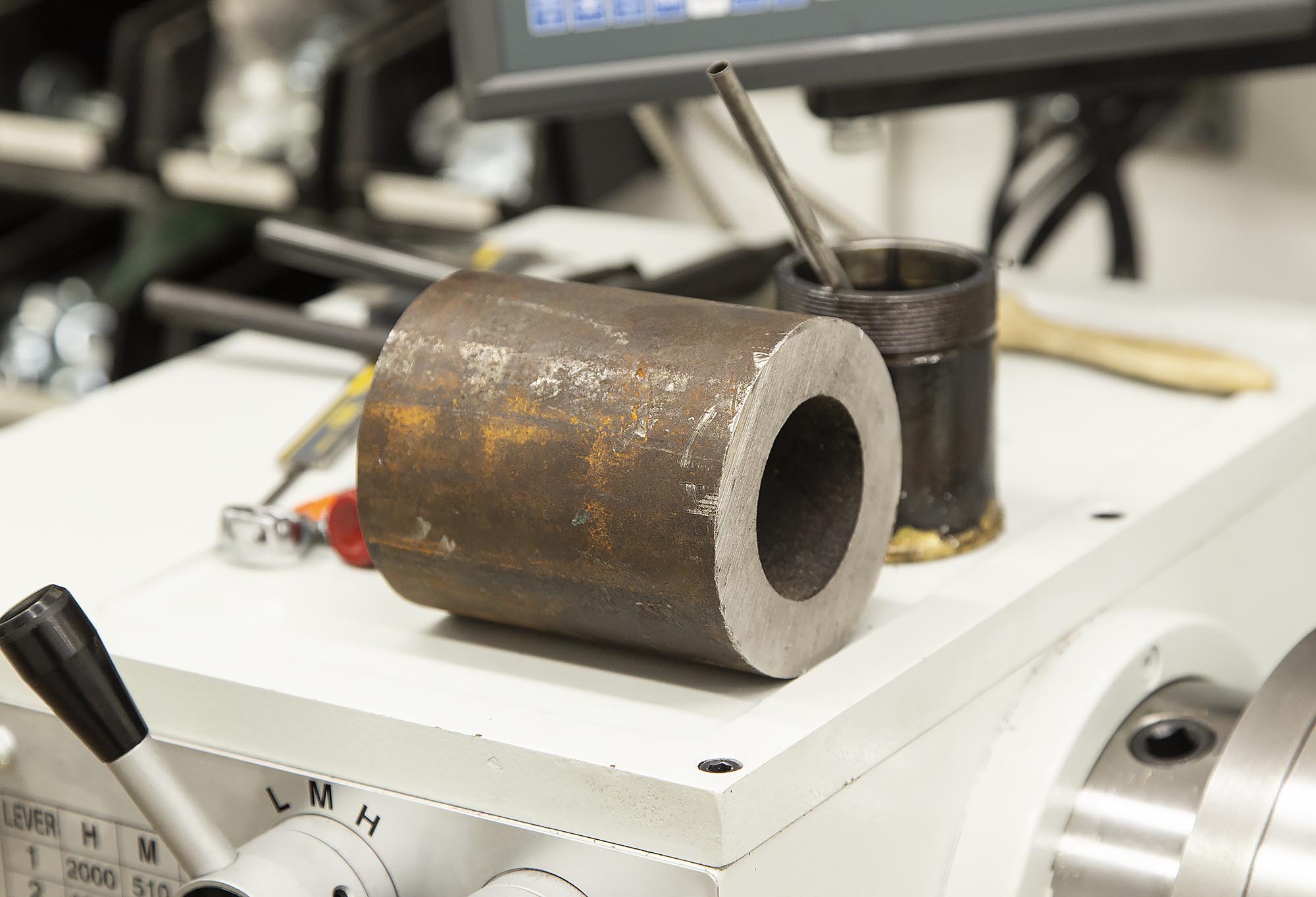
I machined my lathe spider from DOM steel tubing. DOM stands for “Drawn Over Mandrel”. I figured I should start with stock that was as close as possible to the final profile in order to minimize cost, and also minimize machining time. I ordered my DOM tubing from Speedy Metals:
3-1/2″ OD {A} x 2.000″ ID {B} x .750″ Wall {C} Steel Tube-By the Inch SKU: dom3.5x.75
I ordered 4″, and the total came to $29.28 before shipping.
From Altro Steel:
A513-T5 DOM Tube
Alro stocks A513 Type 5 Drawn Over Mandrel Tubing. DOM Steel Tube is produced using uniformly high quality C1020 carbon steel strip and is formed and electric resistance welded into its basic shape. After annealing to produce a uniform grain structure throughout, the tube is then cold drawn over a mandrel to give it these advantages: uniform concentricity around the central axis, better ovality, closer tolerances, denser surface, uniform wall thickness, and higher physical properties. The cold working process works the weld area to produce a sound, dense, and homogeneous structure comparable to that of the base metal.
The weld line disappears, causing DOM tube to be virtually seamless. The surface is superior to that of regular seamless tubing, since the material has been cold drawn from strip steel. The hole is straight and concentric with the outside diameter. DOM Steel Tube may be machined, formed, welded, carburized, and subjected to other fabricating techniques that are ordinarily applied to low carbon steel. The use of DOM Steel Tube gives you a guaranteed micro-inch surface and lower productions costs by reducing or eliminating such operations as boring, honing, and finishing.
As it turns out, this A513 steel machines really nice!
Equipment and Tools
For this project, I used the following tools:
- Precision Matthews PM-1440GT Lathe
- Precision Matthews PM-949TV Mill
- Micrometer set: 0-1″, 1-2″, 2-3″
- Accusize Industrial Tools 5/8” Shank 7 Pc Indexable Carbide Turning Tool Set in Fitted Box, 2387-2005
- 3/8″ carbide endmill
- Twist drill set
- Cleveland Twist Drill 3/8″ x 16 3-flute through hole tap
Machining the Spider
First Steps
I chucked the DOM tubing up in the lathe, and proceeded to:
- Face the end (rough bandsaw marks) to a uniform finish
- Turn down the OD of the DOM tubing (enough to remove the rusty layer and uniform the OD)
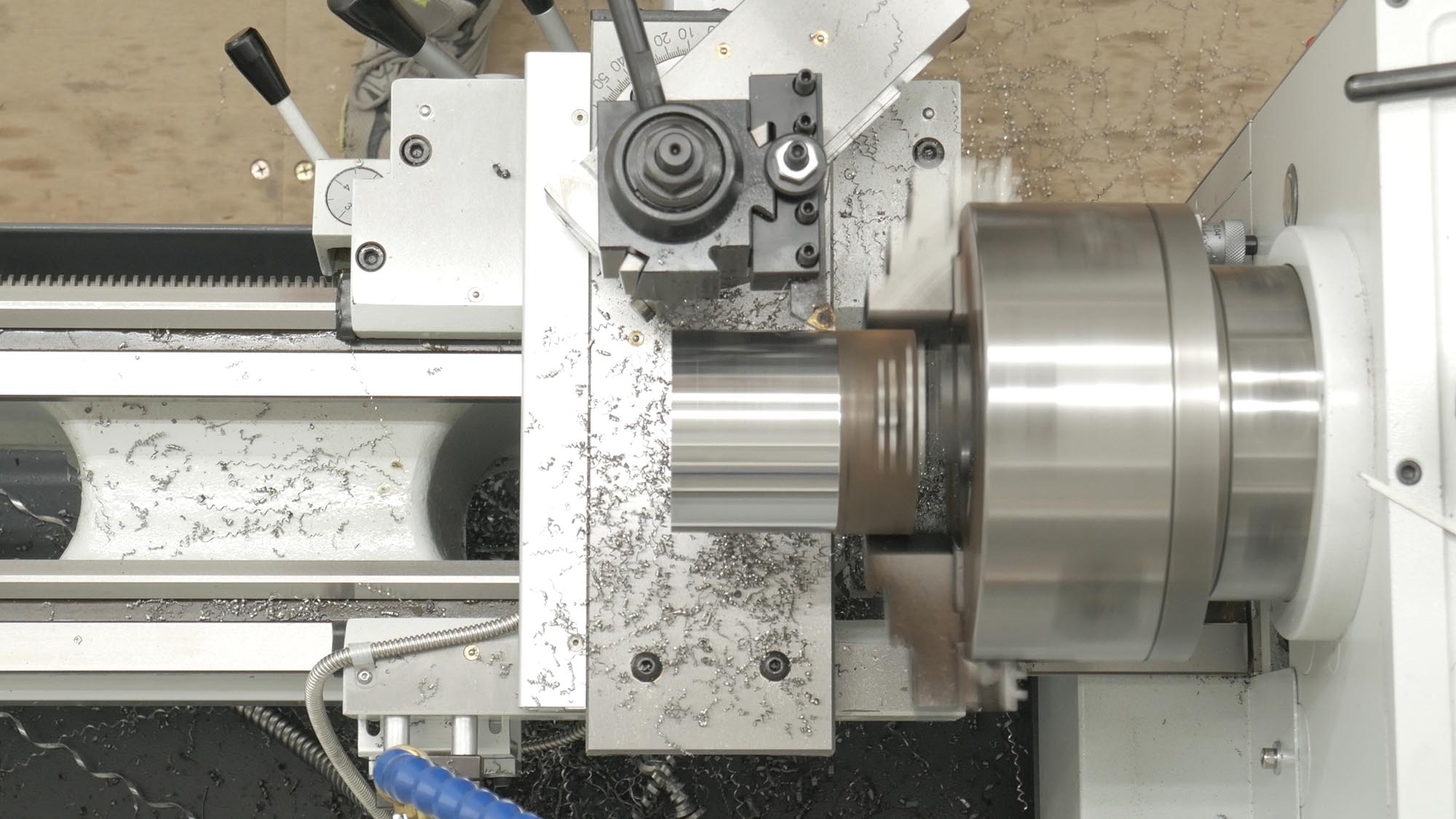
Boring the Counterbore
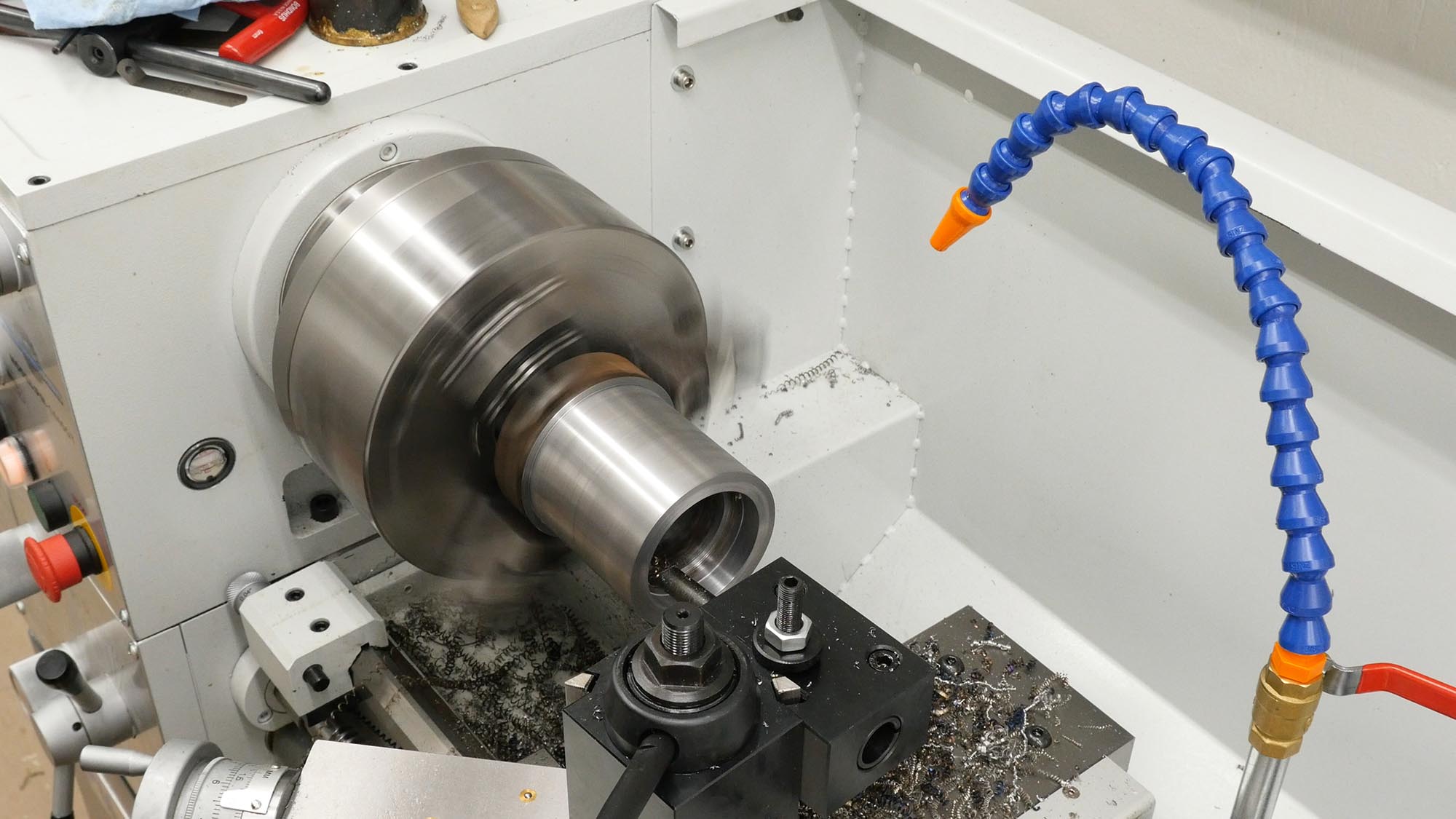
After the primary surfaces were trued and turned to the proper dimensions, I bored out the counterbore which would form the mating surface between the spider and the outside of the lathe spindle. I turned the counterbore to 0.002″ over the OD of the lathe spindle. If I were to do this again, I would turn it to 0.0002″ over the lathe spindle diameter or close to it.
Cutting off The Spider Body

The strategy for this spider build was to chuck up the DOM tubing once for the primary turning work, and that worked out great. After these initial steps, it was time to cut the “clamping end” of bare DOM tubing free from the machined body of the spider. The important thing here is to get the cut in the right place! I didn’t want it to be too short, or to have to machine a bunch off the end. It worked out perfect: measure four times, cut once (like the woodworking adage, modified for metalworking).
Milling the Flats, Drilling and Tapping Set Screw Holes
At the outboard end of the spider, there are four set screws (with aluminum tips) that clamp and secure the work being machined (or the stock tube that in turn holds the work from whipping). I used four 3/8×16 set screws and machined four “thumbscrews” (really thumb nuts) to secure the setting for each set screw. The first order of business was to mill the flats:
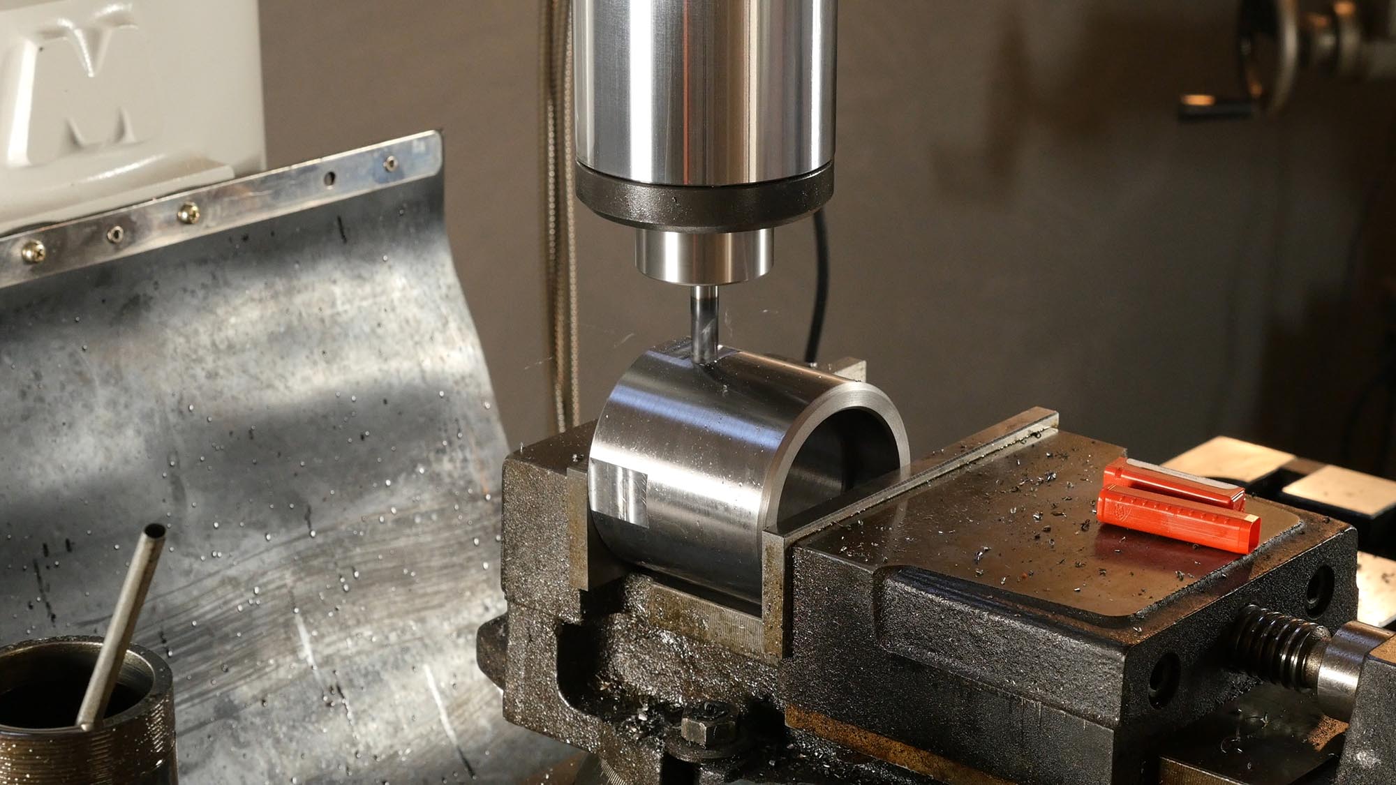
By carefully using parallels and a square, I was able to dial in the angle between each flat plenty close. A fixture like a spin index or rotary table could be used here. I then drilled the holes that would be tapped in the center of each flat:
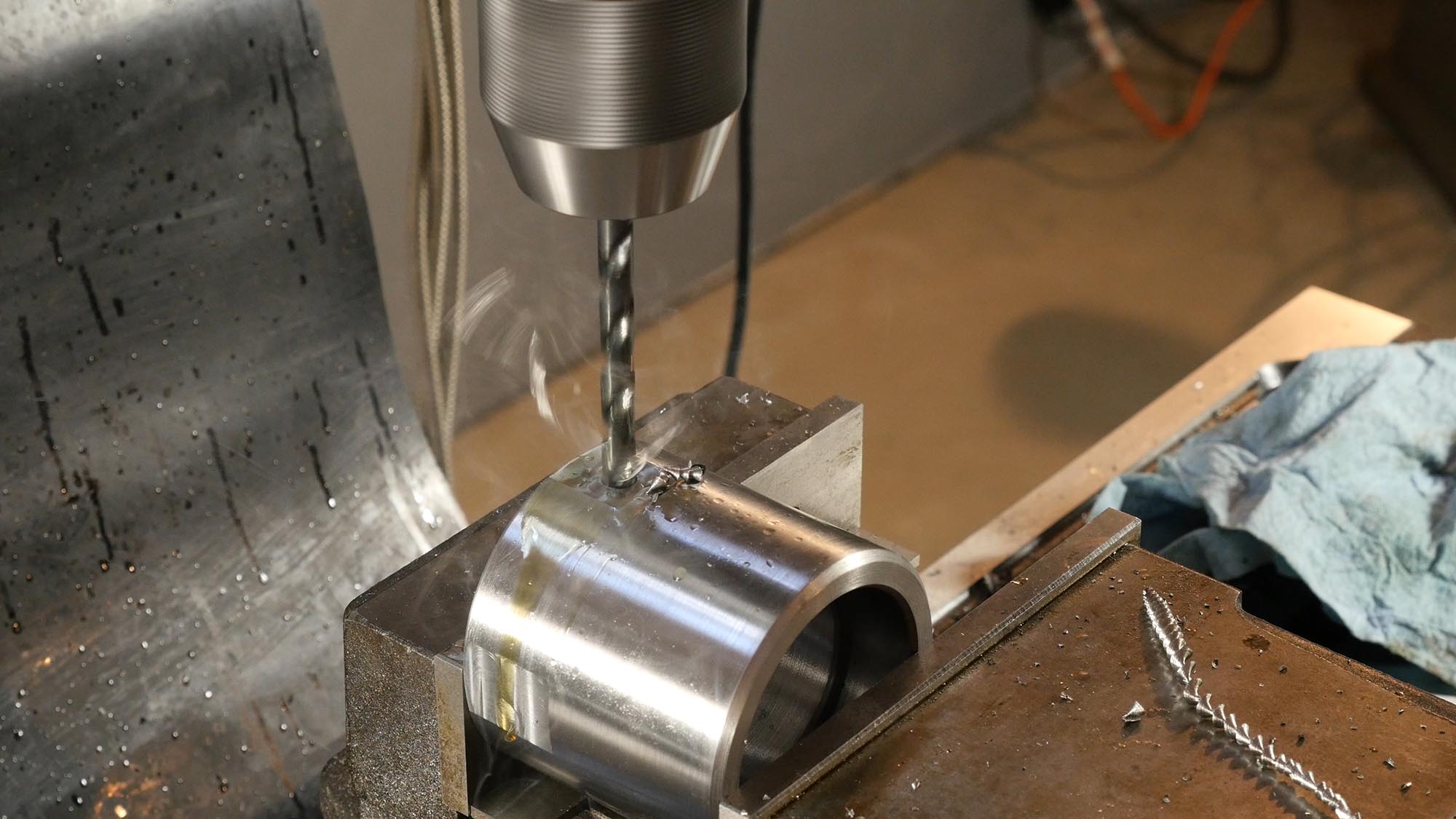
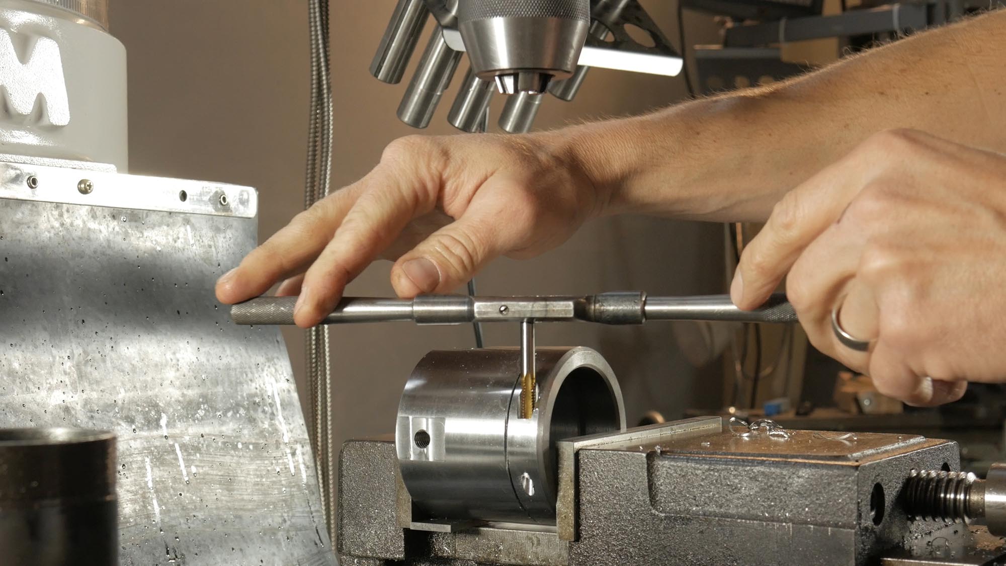
Time for some power tapping! I engaged the back gear for the PM-949TV mill, and slowed the machine down to near minimum speed. Using a 3/8″ 5C collet, I held the tap securely (and with great axial alignment):
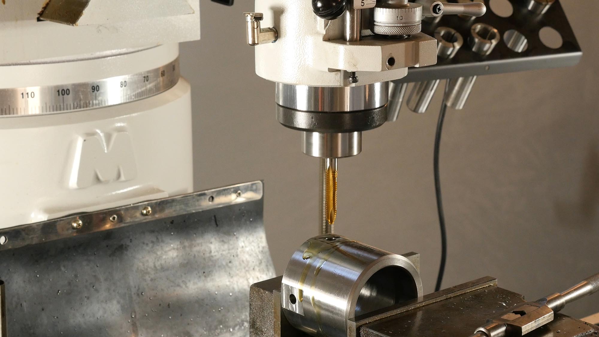
All you have to do is use the quill to get the tap started, wait until tapping is done, turn off the motor, and then reverse the motor. It’s basically an automatic operation! It’s VERY important to use a quality tap for this kind of work. It will produce a better hole, and take less torque compared to junk taps. This is a USA-made Cleveland Twist Drill 3-flute TiN coated tap that I’ve used for years.
Cutting the Primary Clamp Slit
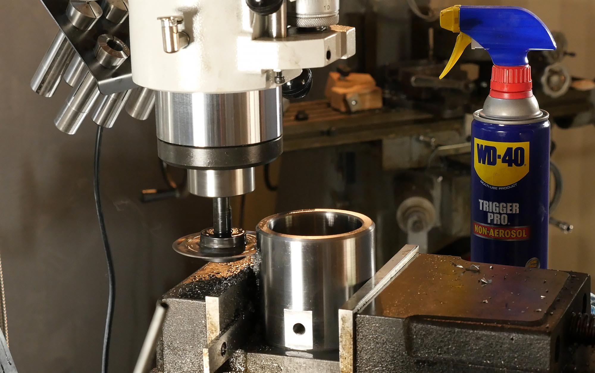
For this job I used what I had on-hand- some old slitting saws from Grandpa. These weren’t in very good shape, so I went slow and used a lot of WD-40 as ad-hoc lube and coolant (not the best, but works fine). I used power feed and several passes to make the slitting cuts.
Counterboring, Drilling, and Tapping for the Clamp Bolt
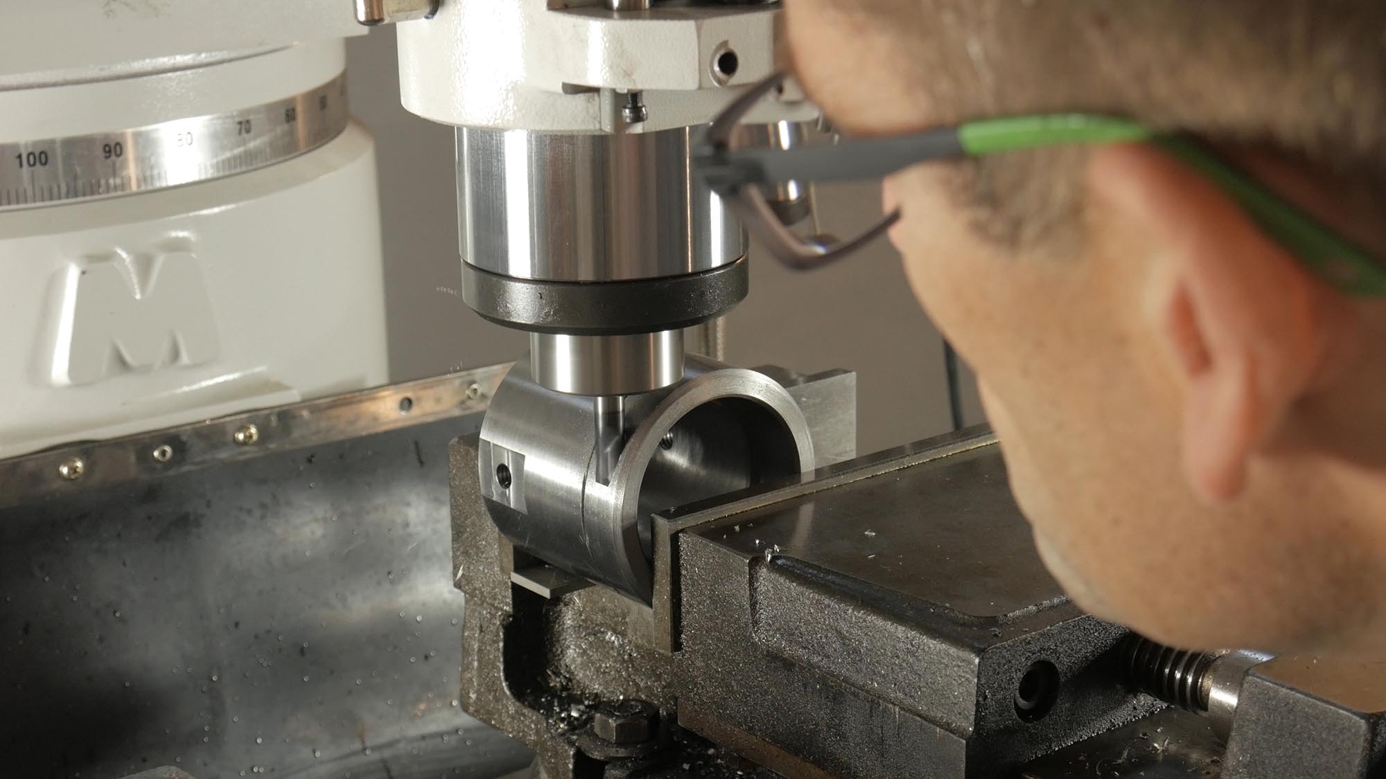
This spider design uses a single 1/4×20 allen-type cap screw. In order to machine the features for this “cross bolt clamp” setup, I started with a plunging cut using a 3/8″ carbide endmill. You have to be careful when making plunge cuts like this since endmills aren’t really designed for these kinds of cuts. Normally I would drill first, then use the endmill more like a counterbore, but due to the profile of the cylinder I was working with here, I decided to try the plunge. It worked just fine!
Then it was time to drill the two holes:
- The tap clearance hole (minor diameter)
- The body clearance hole (major diameter)
I used power downfeed for all of the drilling during this project.
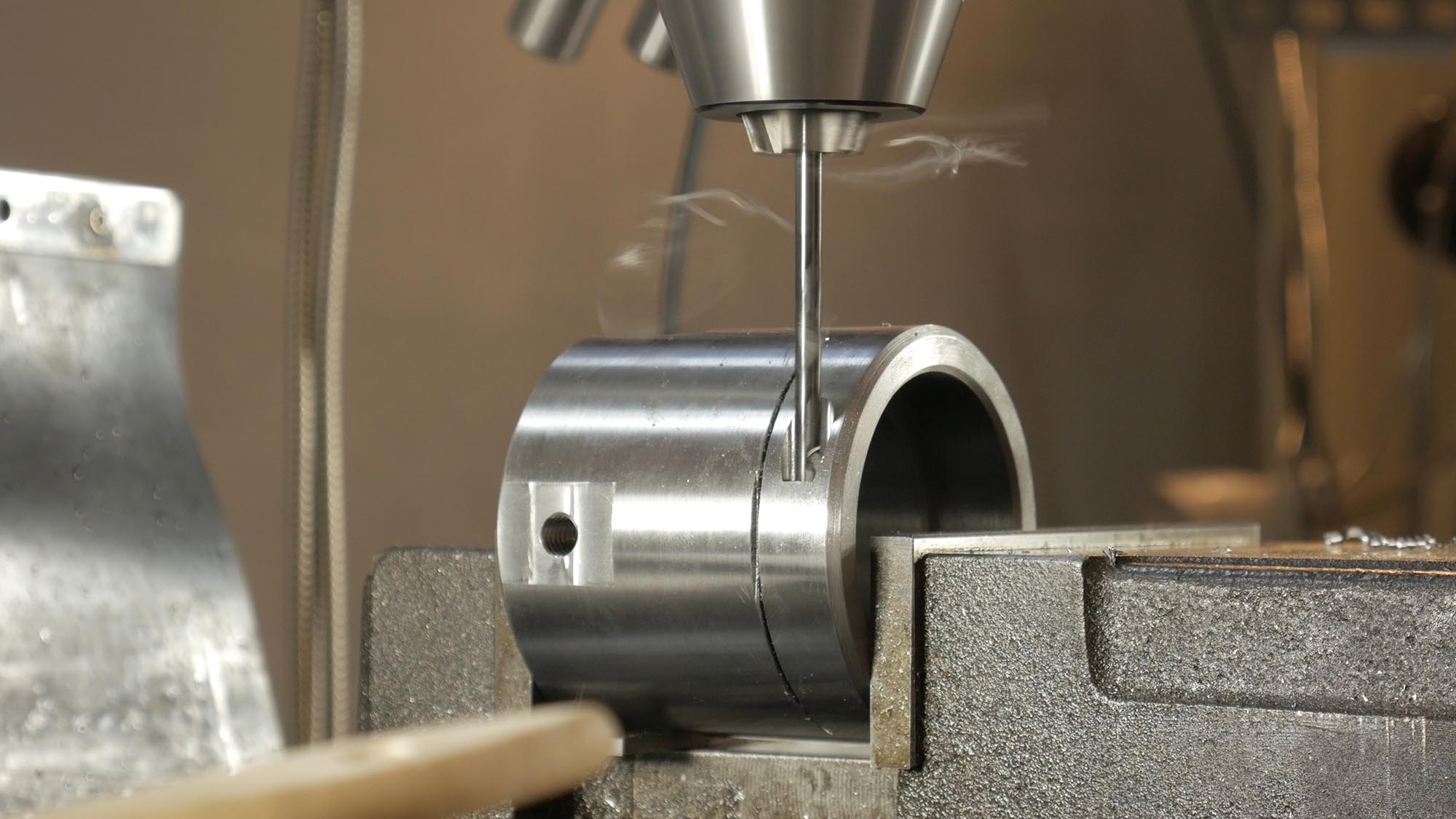
And finally, I ran a 1/4″ 20 tap down through the entire hole feature. Again, I’m using a Cleveland Twist Drill USA-made tap here. Cuts very easy! The body diameter hole here acted as a great “tuide” for the tap. I had to finish things off with a nose-type tap holder due to the clearance around the spider body, no problem!
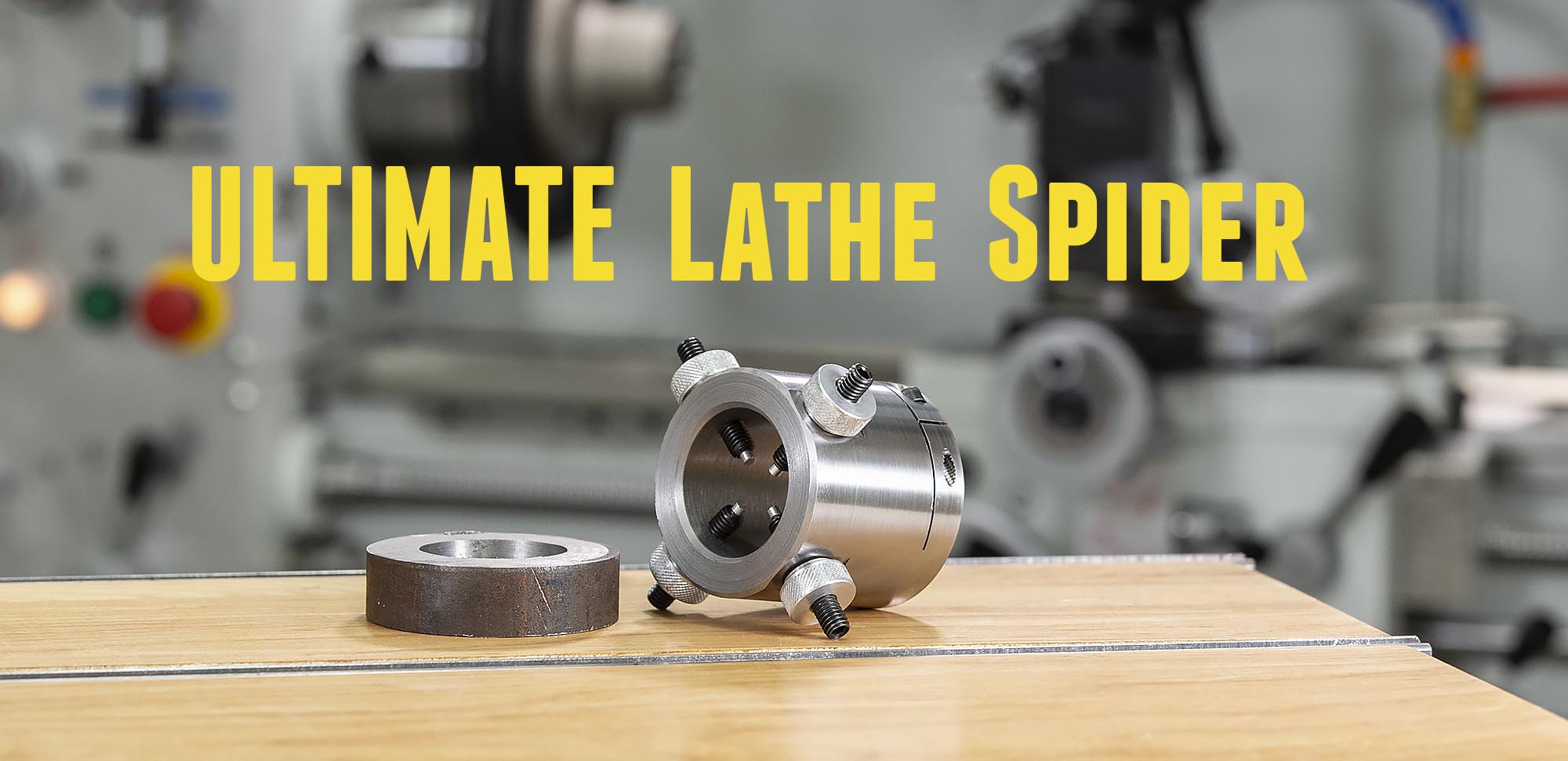
The Finished Product

It’s hard to believe these two chunks of metal (see picture above) came from the same hunk of DOM tubing! It was a very rewarding experience to use my machine tools to make this machine accessory, and at this point I was really eager to put it to use. But I had one more thing to do: open up the side cover of the Precision Matthews PM-1440GT lathe to allow clearance for the spider body!
Precision Matthews PM-1440GT Side Cover Mods
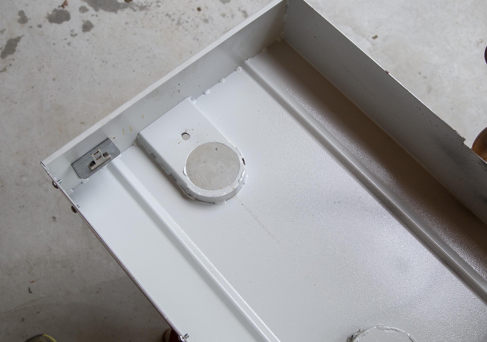
The Precision Matthews PM-1440GT ships with a side cover that has close clearance for the outboard end of the spindle. Here’s what the inside looks like from the factory:
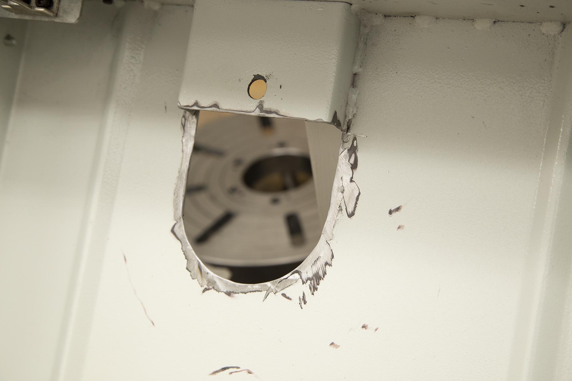
I chose to use a cutoff wheel on an angle grinder to open it up as follows. Note the metal left under the top hole so that the factory thumb screws still have enough metal to hold the side cover on:
I did not have to enlarge the opening around the circumference, it was more like cutting off the inner lip. After the cutting was complete, I masked the inside and outside of the areas where I had done cutting, and spray painted the edges to prevent corrosion, and to enhance the appearance of my job:
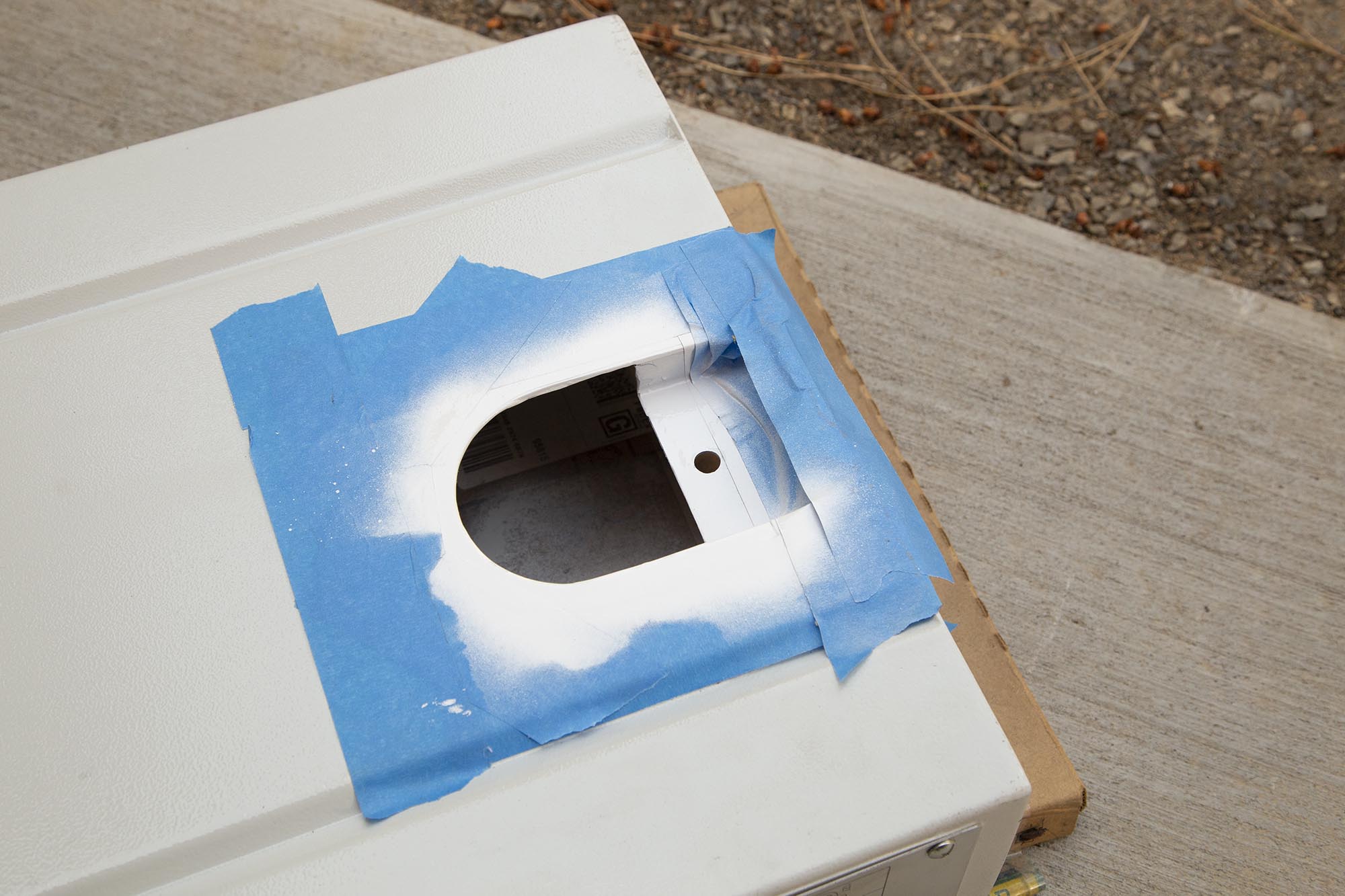
I also drilled a small hole on the top of the side cover right above where the pinch clamp bolt head sticks up. That was I can use a long Allen key to tighten and loosen the pinch clamp bolt. Slick!
I have used this spider now on several rifle builds and many other projects- I wouldn’t be without one!
Improvements
The only real improvement I’d think about making would be to cut the counterbore a bit tighter to the OD of the lathe spindle. A 0.0002″ tolerance would work great. However, the clamping action works great on the spider I built, and I have no regrets. I’m very happy with how this spider turned out. I hope this is useful to those of you that need to build “The Ultimate Lathe Spider”. Thanks for reading!
Don’t miss out on Making With Metal updates, make sure you’re subscribed!
Thanks,
Gavin


Very nice! Now I’m subscribed to yet another site!
I’m reminded I need to get back to working on my own hobbyist machining area…
Awesome, and good luck with your space!
Hi Gavin!
I finally order my 14x40GT and it will be in by the end of this mount, I would like to know if you can built the same ultimate spinder. I don’t a have the tool to built that. If you can let me know.