Sometimes you have to do a lot of “prep work” to get to the “fun work”. Well, after building out our build-sheet, and preparing and aligning the barrel, we’re now to the fun part of this build! That’s right, it’s time to start machining the tenon, and cutting the chamber!
Series navigation:
- 224 Valkyrie Remington 700 Build P1: Planning the Build
- 224 Valkyrie Remington 700 Build P2: Barrel Prep and Alignment In the Lathe
- 224 Valkyrie Remington 700 Build P3: Chambering and Machining (you are here)
- 224 Valkyrie Remington 700 Build P4: Muzzle Threading and Barrel Install
- 224 Valkyrie Remington 700 Build P5: Custom Thread Protector
- 224 Valkyrie Remington 700 Build P6: KRG Bravo Stock, TriggerTech Special Trigger
- 224 Valkyrie Remington 700 Build P7: AICS Magazine Conversion
- 224 Valkyrie Remington 700 Build P8: Barrel Break In, First Groups, First Loads
- Athlon Midas TAC 6-24x50mm HD Riflescope: In-Depth Overview
Disclaimer
Ultimate Reloader LLC / Making with Metal Disclaimer: (by reading this article and/or watching video content you accept these terms)
- The content on this website (including videos, articles, ammunition reloading data, technical articles, gunsmithing and other information) is for demonstration purposes only.
- Do not attempt any of the processes or procedures shown or described on this website.
- All gunsmithing procedures should be carried out by a qualified and licensed gunsmith at their own risk.
- Do not attempt to repair or modify any firearms based on information on this website
- Ultimate Reloader, LLC and Making With Metal can not be held liable for property or personal damage due to viewers/readers of this website performing activities, procedures, techniques, or practices described in whole or part on this website.
- By accepting these terms, you agree that you alone are solely responsible for your own safety and property as it pertains to activities, procedures, techniques, or practices described in whole or part on this website.
Heading to the Lathe
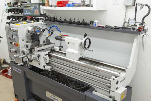
For the breech end of the barrel, we have quite a few steps to perform before this barrel will be ready to install on the rifle. I’m using a Precision Matthews PM-1440GT ultra-precision Taiwanese lathe for this project:
For reference, this is what the end of the barrel blank looks like on the breech end after the initial facing pass, but before the features are machined:

And here’s a diagram showing the finished breech end of the barrel, and the various features we’ll be working on: (breech end shown just after chambering)
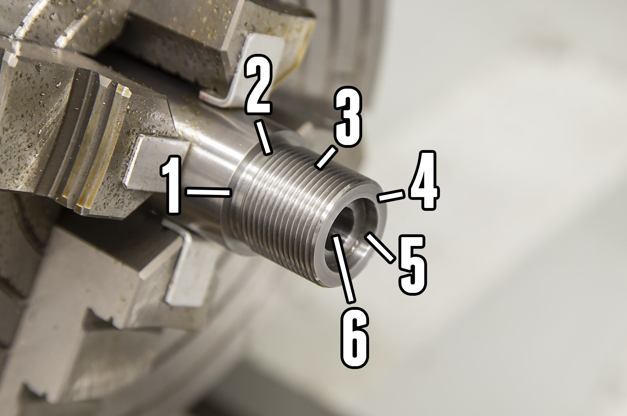
The features shown above are:
- Tenon shoulder
- Thread relief
- Tenon threads
- Tenon face
- Counterbore
- Chamber
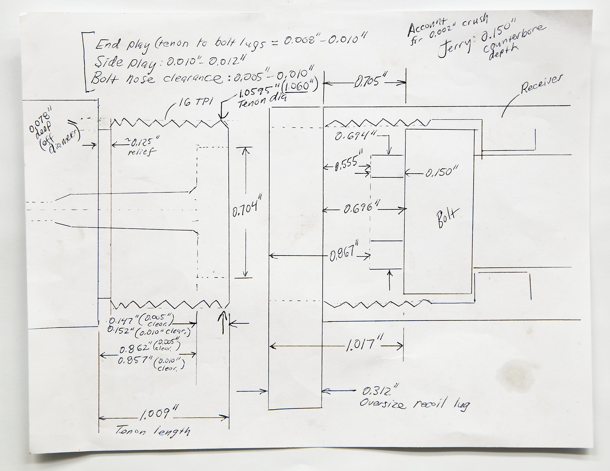
And for review, here’s the build sheet I put together outlining the key dimensions involved: (dimensions for example purposes, do not use on your own rifle build)
Finally, it’s time to do some machining! Here’s the order of operations I used:
Turn down the tenon where the threads will be, cut to 0.020″ longer than the spec from the build sheet (tenon will be faced to length)
Then it’s time to cut the thread relief (right next to where shoulder will be)
I do this with a parting blade (0.125″ in this case), slow spindle speed, lots of cutting oil, and manual in-feed. Setting the X-axis on the DRO to “0.0000” with the parting tool just touching the OD of the tenon allows precise control over thread relief cut depth. Following this, I cut the shoulder with the same tool (made for cutting up to a shoulder) that I used to turn down the tenon OD.
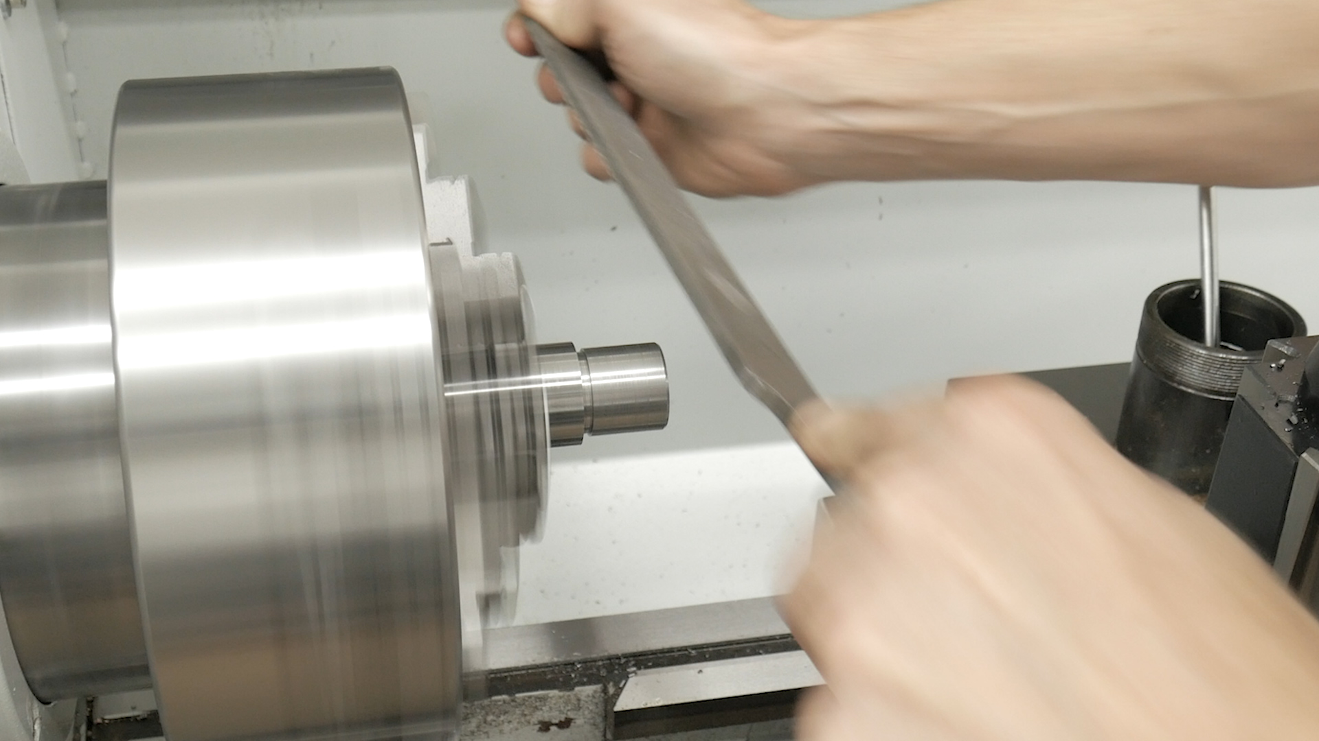
Next, I file a 45 degree chamfer at the end of the tenon where the tenon threads will start. You can also cut this with a lathe tool (just set the compound over to 45 degrees), but filing works well.
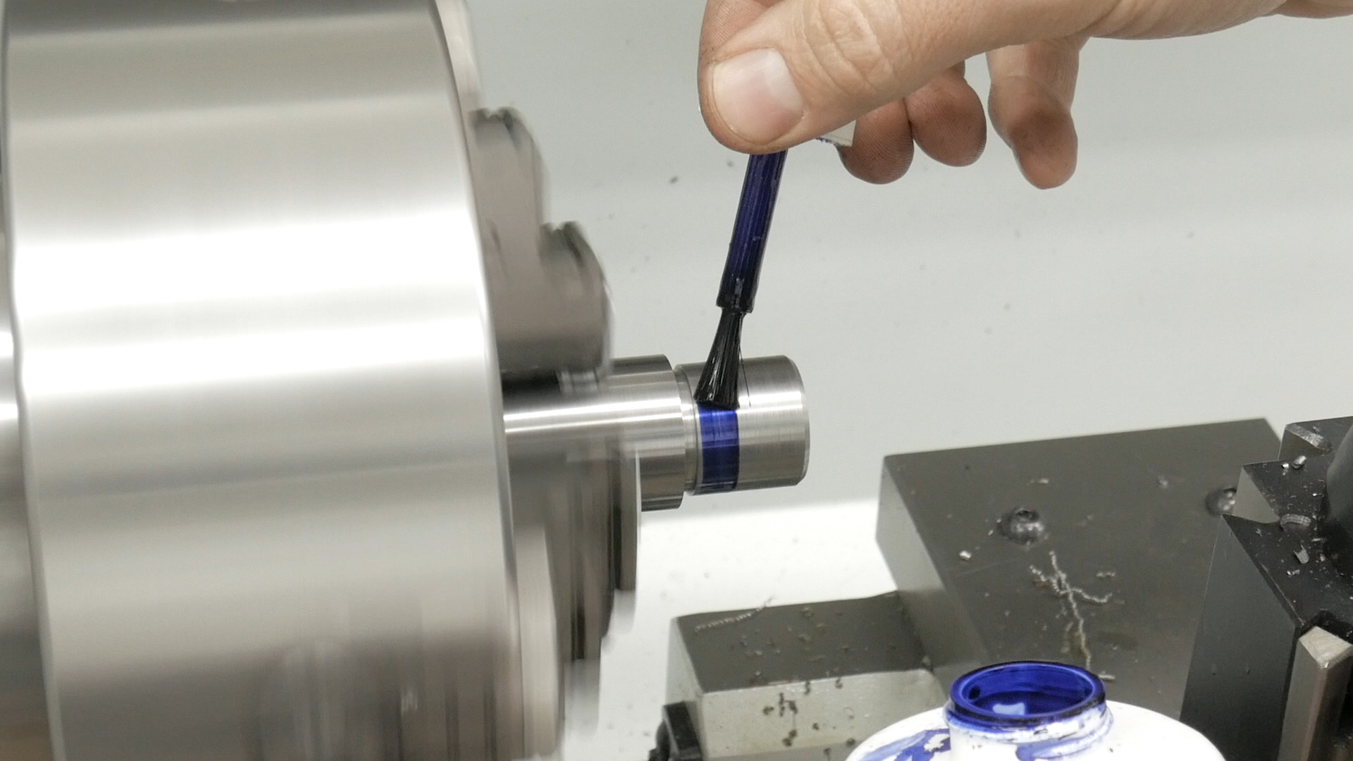
At this point, I was ready to start the tenon threading. In order to validate my lathe setup, I like to paint the tenon with Dychem so that I can test the thread pitch:
After this, I perform a single point threading pass at about 0.001″ – 0.002″ depth. Just enough to see the distance between thread cuts. I then take a thread pitch gauge, and check- in this case I was validating that I was cutting at 16 threads/inch:
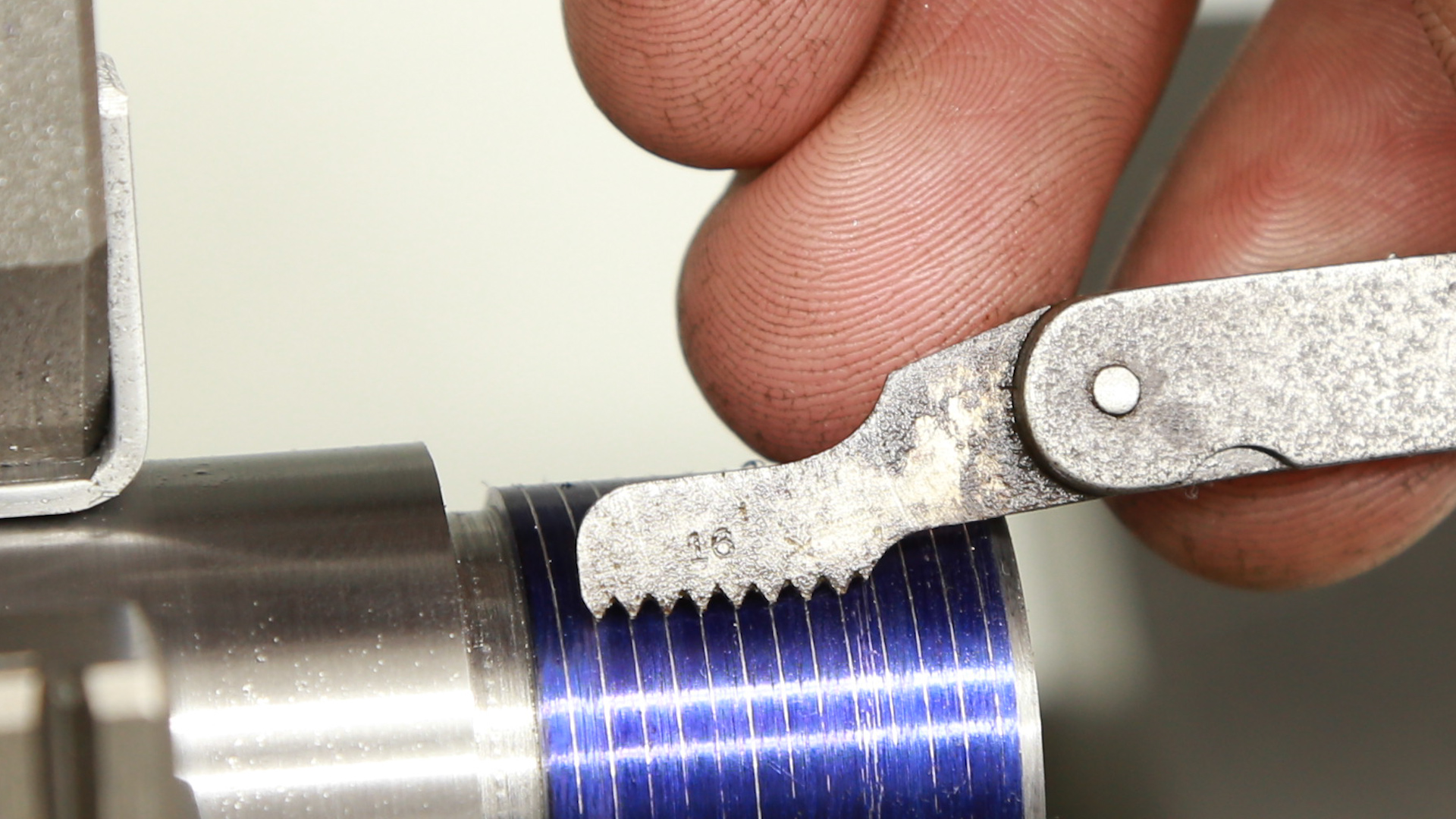
OK, 16 TPI validated! At this point, I was ready for threading. Here’s what I like to do for single point threading when I have a DRO, first the setup:
- Back out the compound slide into about the center of its movement, crank it slightly “in” to take up backlash
- Run the cross slide in to where the tool is just touching the part being threaded (you can see a shiny line on the Dychem)
- Zero the X-axis of the DRO (corresponding do diameter of turned part)
Then for each successive single point threading pass:
- Crank the compound dial “in” between ~0.005″ (start of threading) and ~0.0005″ (final threading passes)
- Engage the halfnuts to initiate carriage travel
- Disengage halfnuts when threading pass is done
- Back the cross slide out about 3 times the final thread depth
- Retract the lathe carriage back to the starting point
- Crank the cross slide “in” until the DRO reads 0.0000″ for the X value (same cross slide position for each pass) – last movement has to be “in” not “out”!
- Repeat starting at step 1 if more thread depth is needed
I’m also going to investigate building a stop for the compound to make step number 6 quicker for each threading pass. You can also use this technique without a DRO, just use the graduated collar on the cross slide, and bring the cross slide to the same value at the start of each pass (being careful to have last movement “inward” to ensure backlash is not a factor in cross slide position).
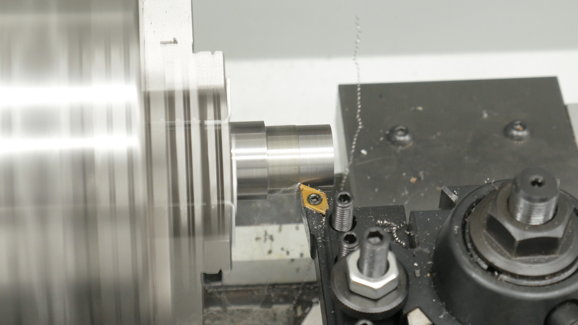
Here’s a picture of a threading pass:

With my carbide threading tool and turning 416R stainless, I found 250 RPM to give great surface finish for these threads.
Here’s my process for monitoring and calculating thread depth:
- Take multiple threading passes, watching the tops of the threads. When the tops are getting somewhat close to a “pointed” profile (without pronounced “flat”), start taking measurements.
- Measure troughs of threads on a take-off barrel if possible, zero-out a digital caliper on these “troughs”
- Use digital caliper to monitor and measure thread depth (approximate, this method is not exact) for each subsequent threading pass.
- When threads are within about 0.005″ of the desired depth indicated by the calipers, start the “screw on the receiver” method for evaluating thread fit.
- For each threading pass, place the recoil lug on the tenon, then screw on the receiver. Initially the receiver will only go on 1-2 threads. Then it will thread on half way when threads are cut deeper. When the receiver will screw all the way against the shoulder and recoil lug, you are done. For the final passes, take off 0.0005″ (as indicated by the compound) or less.
Here’s a picture of testing thread fit with the receiver:

It’s important not to cut the threads too deep- you want a relatively close fit between the receiver threads and the barrel tenon threads!
Now the counterbore can be cut. I like to take multiple passes facing the counterbore to depth with a rigid boring bar, but to cut the counterbore to about 0.010″ under the finished diameter. You can then take a couple longitudinal passes to cut the counter bore to diameter, stopping at the appropriate depth (the depth of the counterbore).
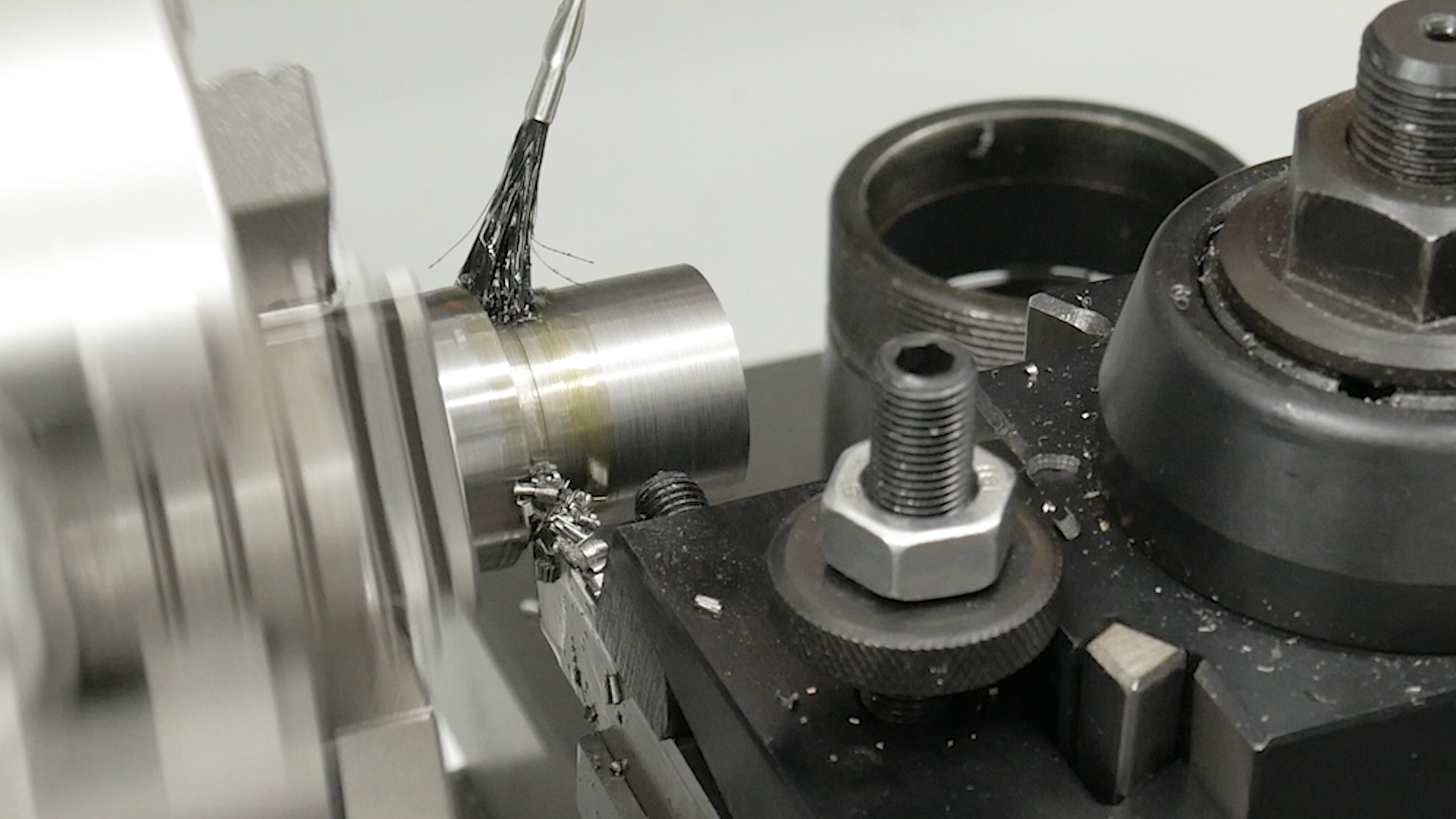
Here’s a picture of cutting the counterbore:
When the counterbore has been completed, it’s time for chambering!
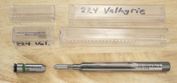
For chambering, I used the following:
- JGS Precision floating reamer holder
- PTG 224 Valkyrie SAAMI spec finish reamer (with removable pilot bushing)
- PTG 9-piece 22 caliber bushing set
- PTG 224 Valkyrie Go Gauge (use Gordy Gritter’s tape trick to make No-Go Gauge as well)
- Twist drill (for pre-drill)
- Boring bar (to clean up pre-drill, make concentric)
- Viper’s Venom high-sulfur cutting oil
I started with a pre-bore of about 0.375″, being VERY CAREFUL not to drill too deep. I then did two boring bar passes to clean up the hold and make everything concentric. Then it was time to put the chambering reamer to work!
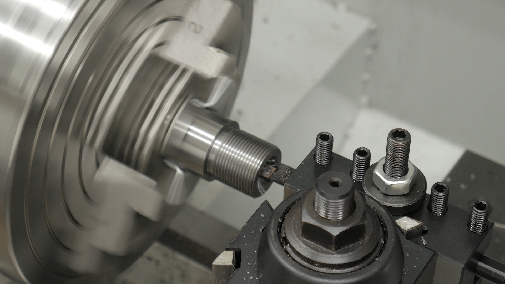
Here’s a picture of the chambering setup:
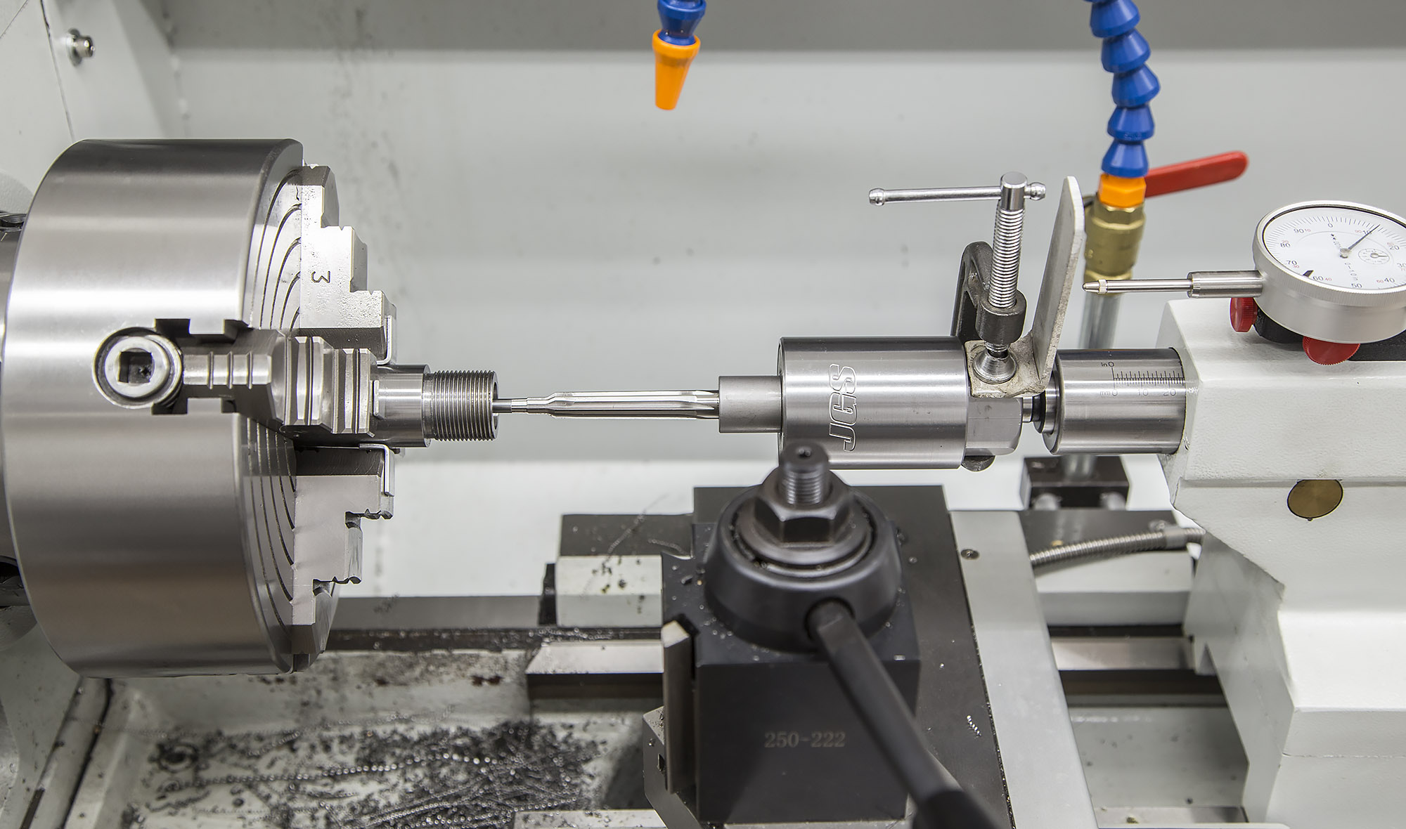
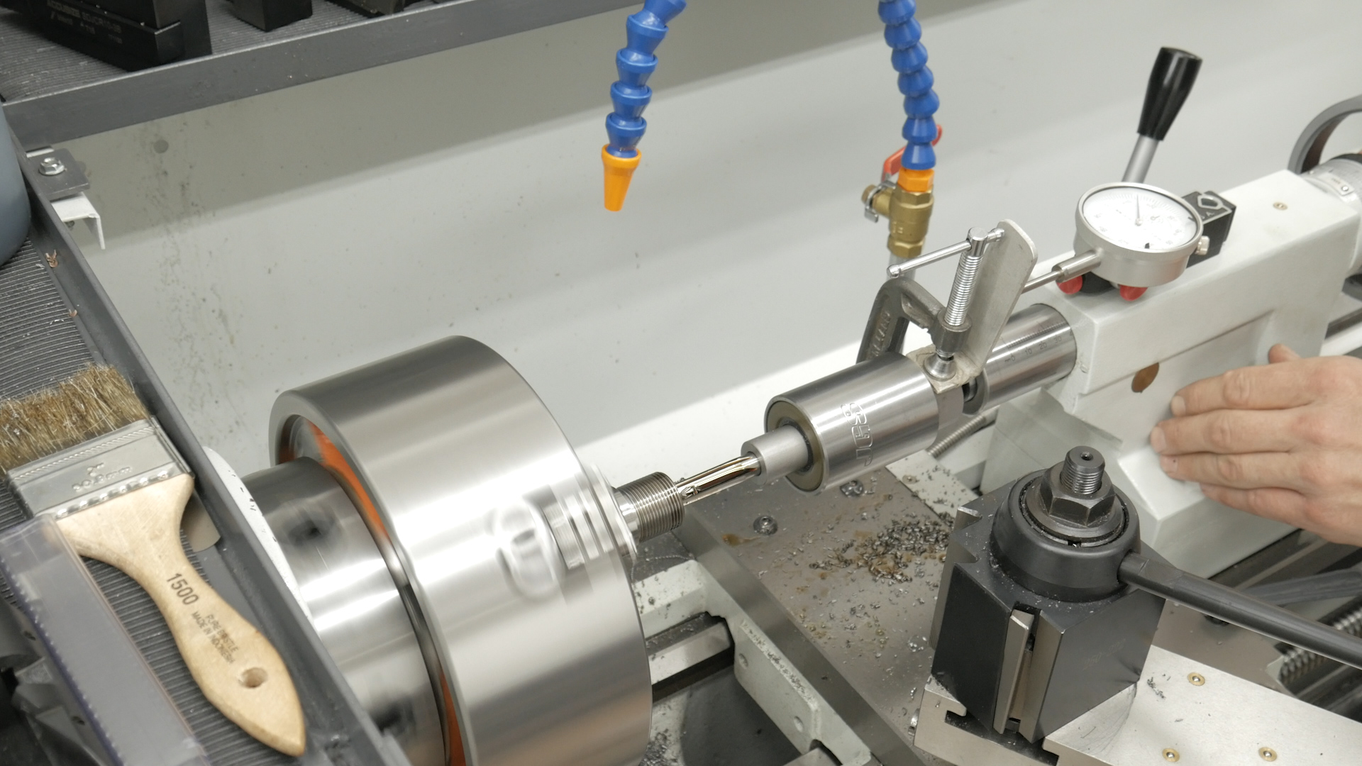
Since I don’t have a pressure flush system, I need to take “short plunges” so that I can clean the chips out of the reamer flutes before they get “jammed up” and cause issues. I used essentially the same process as I did last time (with the Winchester model 70 re-barrel job) but this time I turned the spindle speed up a bit, and started with plunges that were a bit more deep (about 0.070″ per pass). Here’s a picture of the reaming process while it was taking place:
I had zero chatter, and zero “felt runout” on the PTG floating reamer holder while reaming, very smooth. I used my tailstock-mounted dial indicator (with Mighty-Mag and a custom stop/clamp) to monitor reaming depth. This time I did something a tad different: reaming until the bolt would barely close on a “no-go” gauge. Since the no-go gauge is about 0.002″ longer than a go gauge, and I was accounting for about 0.002″ of “crush” then tightening the barrel onto the receiver, I hoped everything would “add up” correctly.
But I still had work to do on the “muzzle end” before I would be able to validate final headspace, and that’s what I’ll cover in the next post… Be sure you’re subscribed.
Thanks,
Gavin