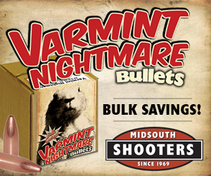
Today we’re loading some match .50 BMG for the Incredible Hulk using Triebel dies! Disclaimer Ultimate Reloader LLC / Making with Metal Disclaimer: (by reading this article and/or watching video content you accept these terms). The content on this website (including videos, articles, ammunition reloading data, technical articles, gunsmithing and other information) is for demonstration […]
Category: RCBS General
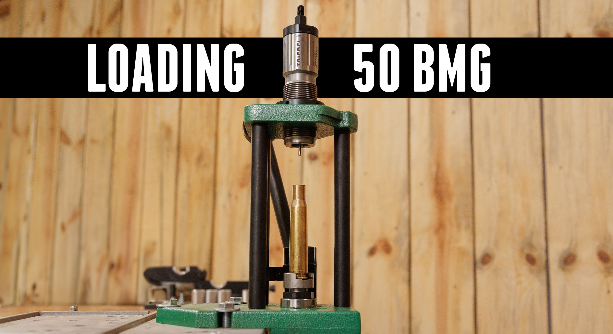
Head to Head: .357 Magnum and .38+P
I recently compared .45 ACP and 10mm. Today I’m pitting .357 Magnum and .38 Special + P against one another! Disclaimer Ultimate Reloader LLC / Making with Metal Disclaimer: (by reading this article and/or watching video content you accept these terms). The content on this website (including videos, articles, ammunition reloading data, technical articles, gunsmithing […]
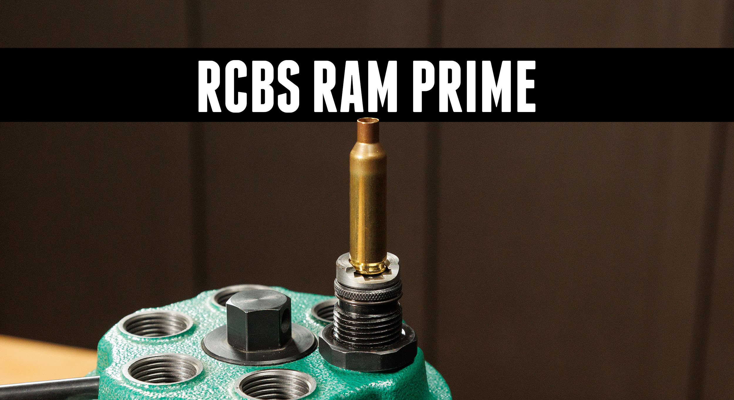
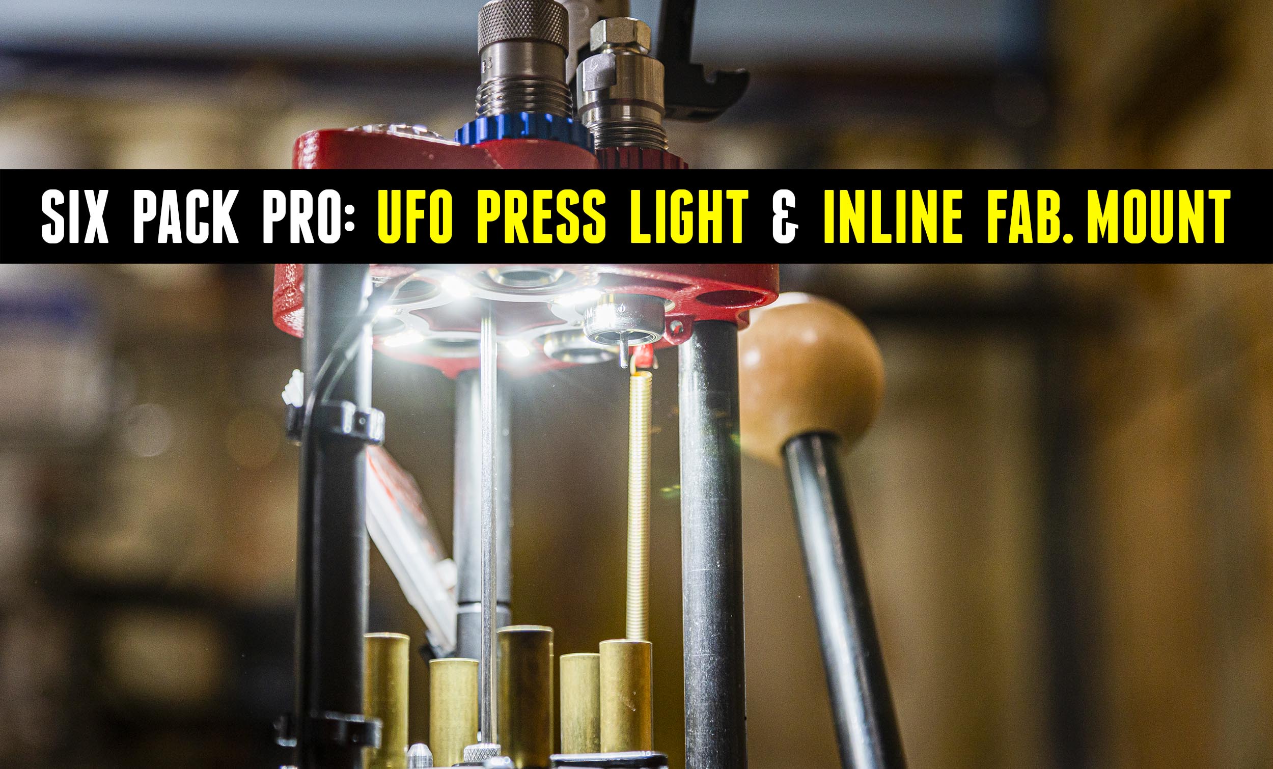
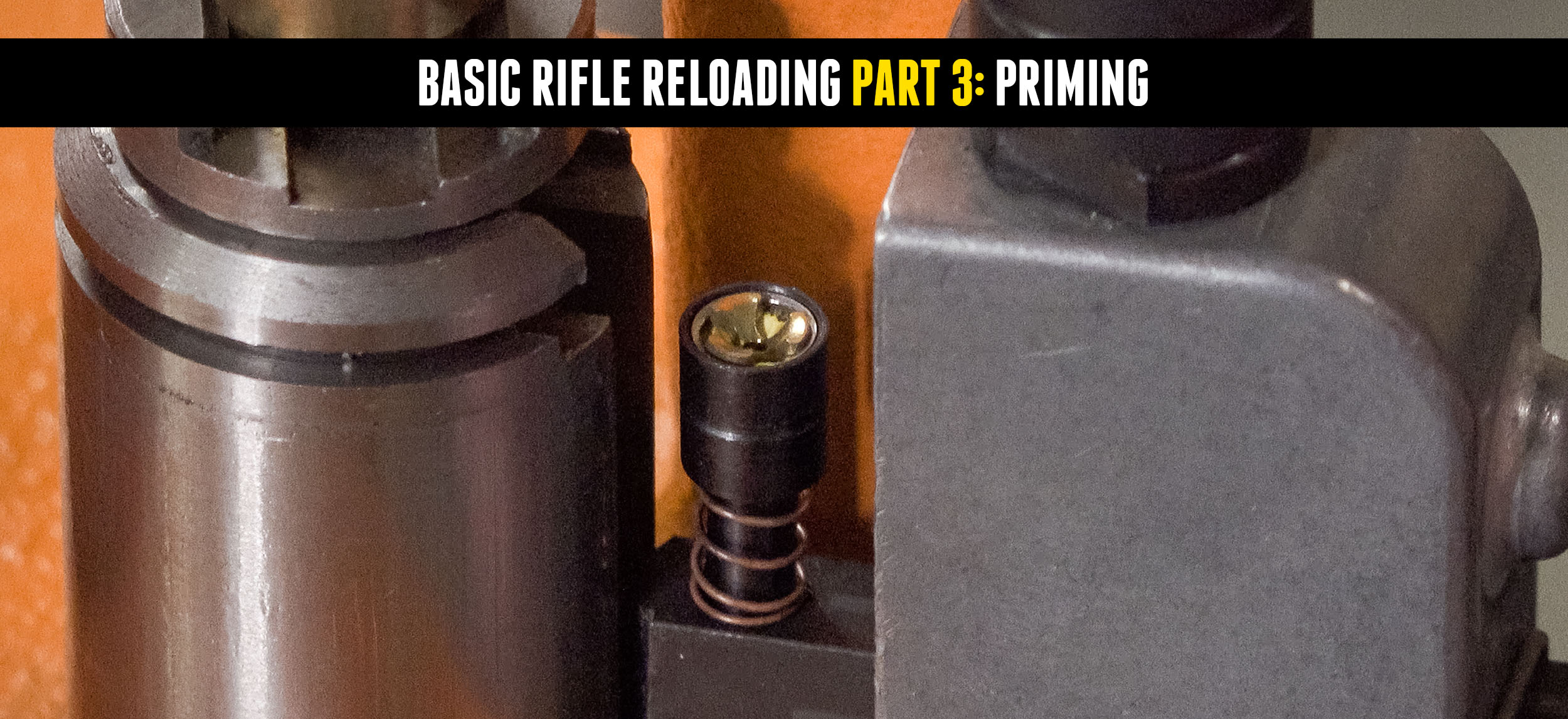
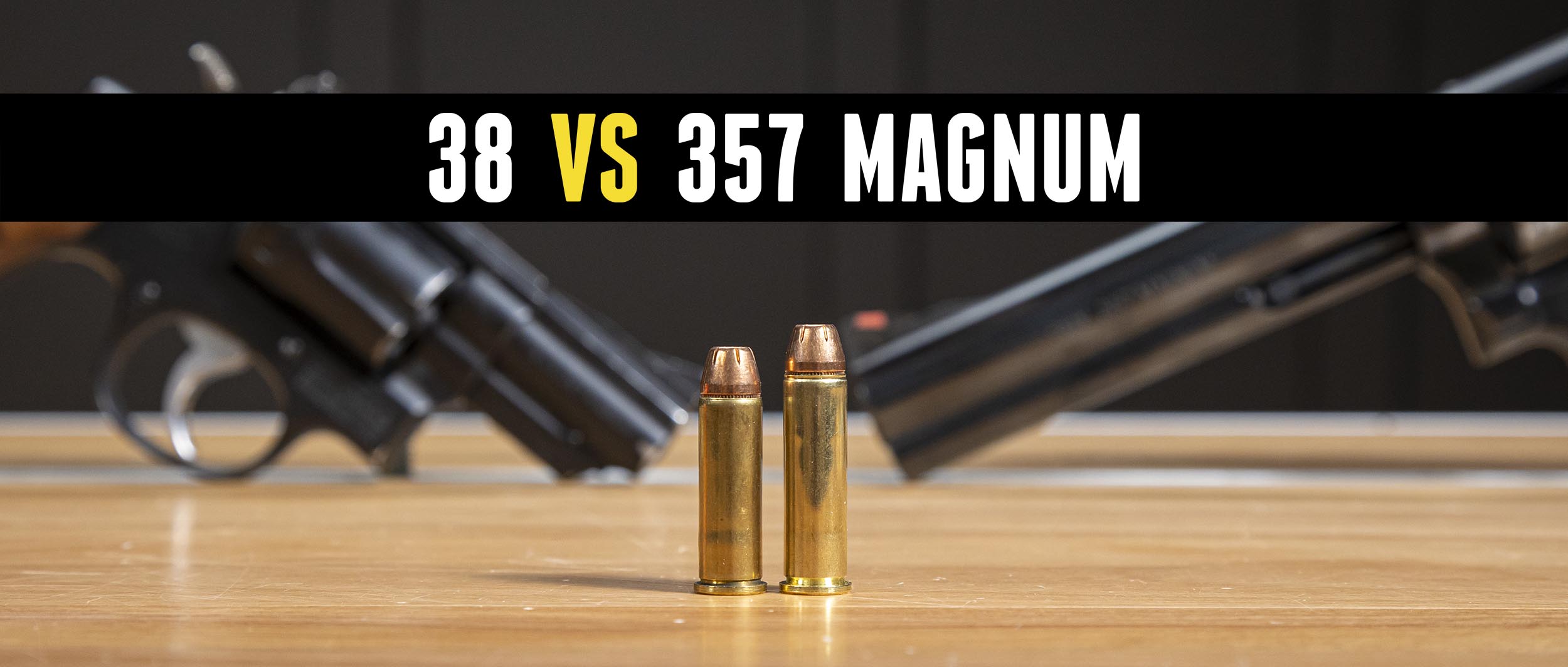
Prime with a Die? RCBS Ram Priming!
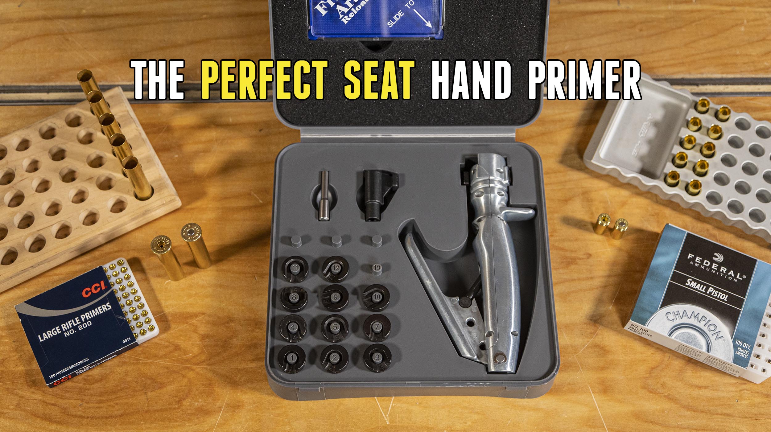
We’ve looked at a number of priming methods including bench-mounted, progressive, and hand priming systems. Did you know you can prime on any press with the RCBS Ram Prime? Disclaimer Ultimate Reloader LLC / Making with Metal Disclaimer: (by reading this article and/or watching video content you accept these terms). The content on this website […]
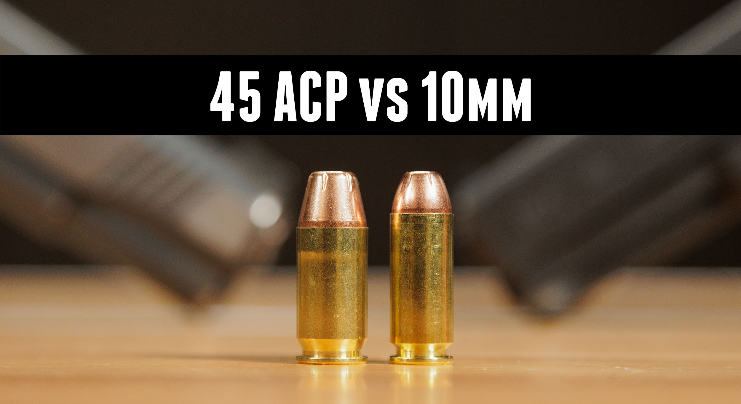
Head-to-Head: .45 ACP vs. 10mm For Self Defense
10mm and .45 ACP are the heavy hitters of the self-defense handgun world. Which is better? Disclaimer Ultimate Reloader LLC / Making with Metal Disclaimer: (by reading this article and/or watching video content you accept these terms). The content on this website (including videos, articles, ammunition reloading data, technical articles, gunsmithing and other information) is […]
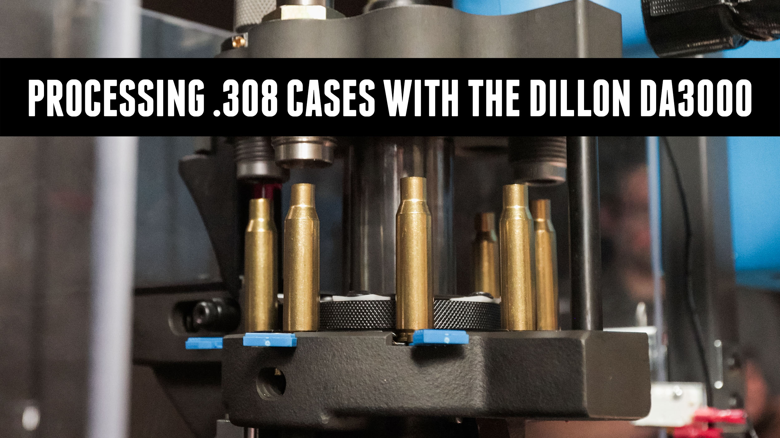
Effortless .308 Brass Processing with the DA3000
Case preparation can take forever and you’re lucky if you find this monotonous process particularly fun. We’re automating it with the Dillon DA3000 and CP2000! Disclaimer Ultimate Reloader LLC / Making with Metal Disclaimer: (by reading this article and/or watching video content you accept these terms). The content on this website (including videos, articles, ammunition […]
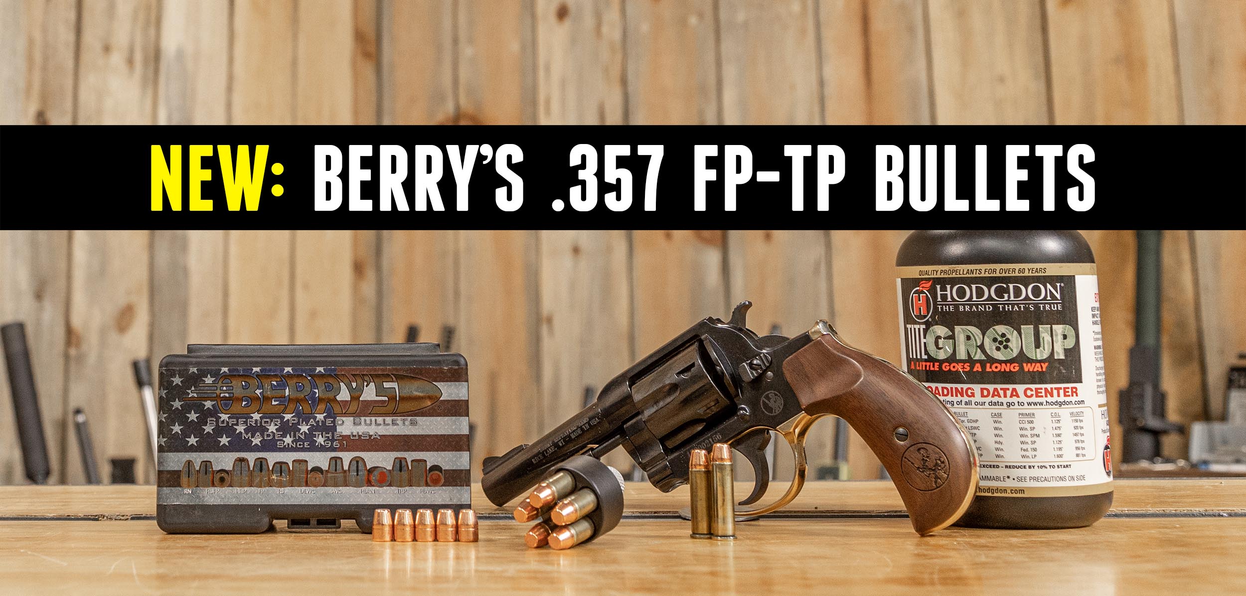
Berry’s 125 gr FP-TP .38/.357 Bullet
We’ve loaded .38 and .357 with Berry’s before, but if you’re looking for a high velocity .38+P or .357 magnum load with modest recoil, Berry’s 125 grain Flat Point Thick Plate bullet is a great option! Disclaimer Ultimate Reloader LLC / Making with Metal Disclaimer: (by reading this article and/or watching video content you accept […]
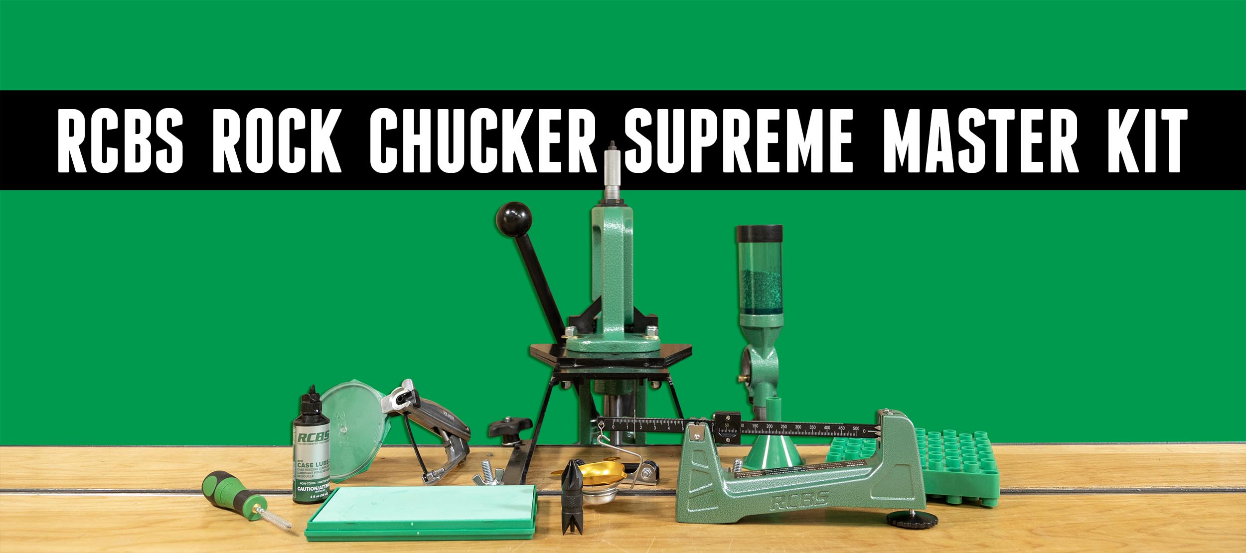
Rock Chucker Supreme Master Reloading Kit
I thoroughly enjoyed looking over the items in this Rock Chucker Supreme Master Reloading Kit and putting them to work. My familiarity with RCBS gear dates back to the 1970s with my father’s RCBS press. In the mid-1980s, I bought my own Rock Chucker press which I still use 40 years later! Disclaimer Ultimate Reloader […]
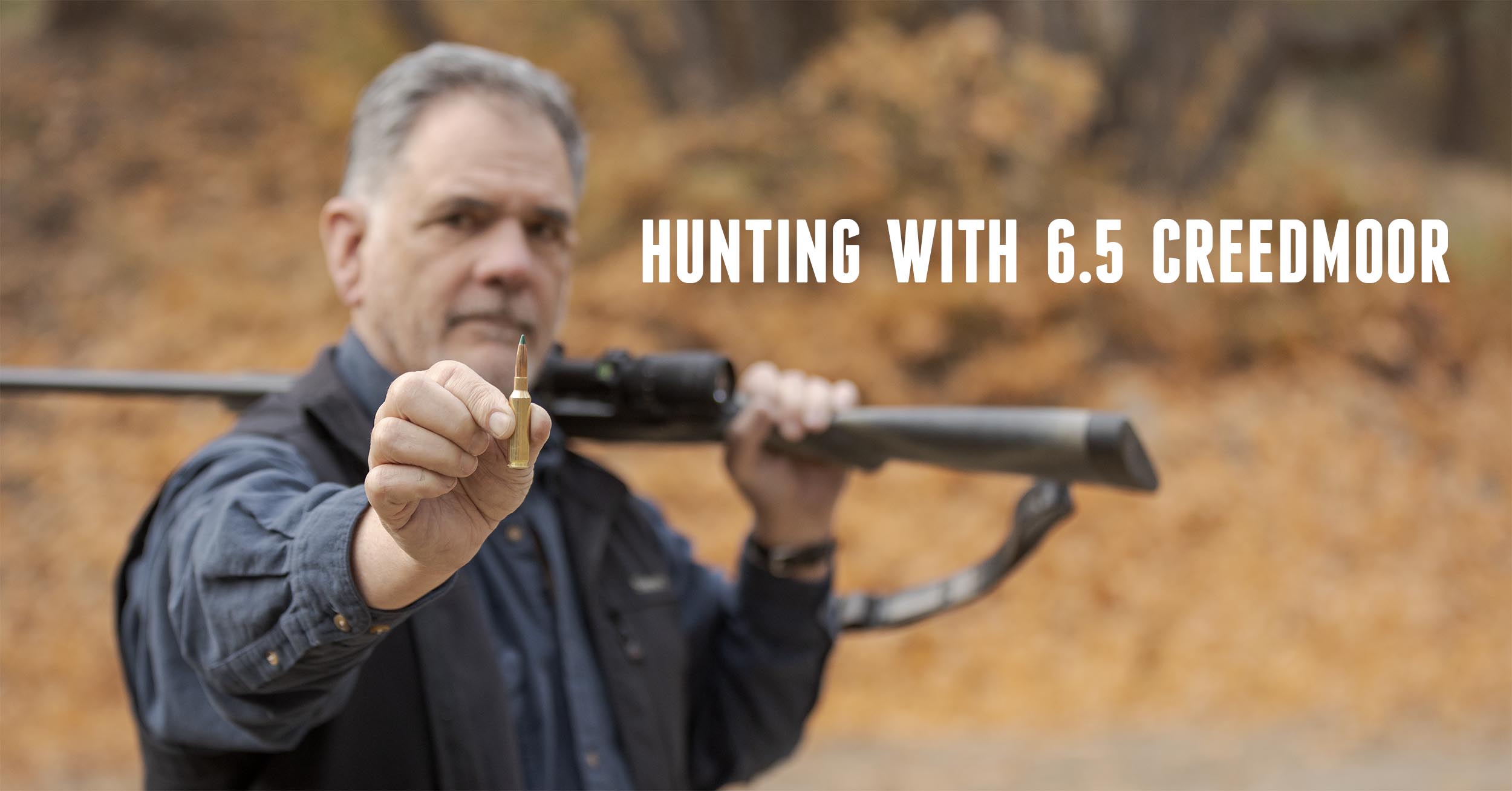
Finally – Guy Miner Hunts with a 6.5 Creedmoor!
You all know how much I love the .30-06. Thanks to Gavin, I have the opportunity to work with a new rifle, new scope, and a cartridge that’s new to me! That’s a lot of “new” for me to deal with, but I am enjoying every bit of it. Disclaimer Ultimate Reloader LLC / Making […]
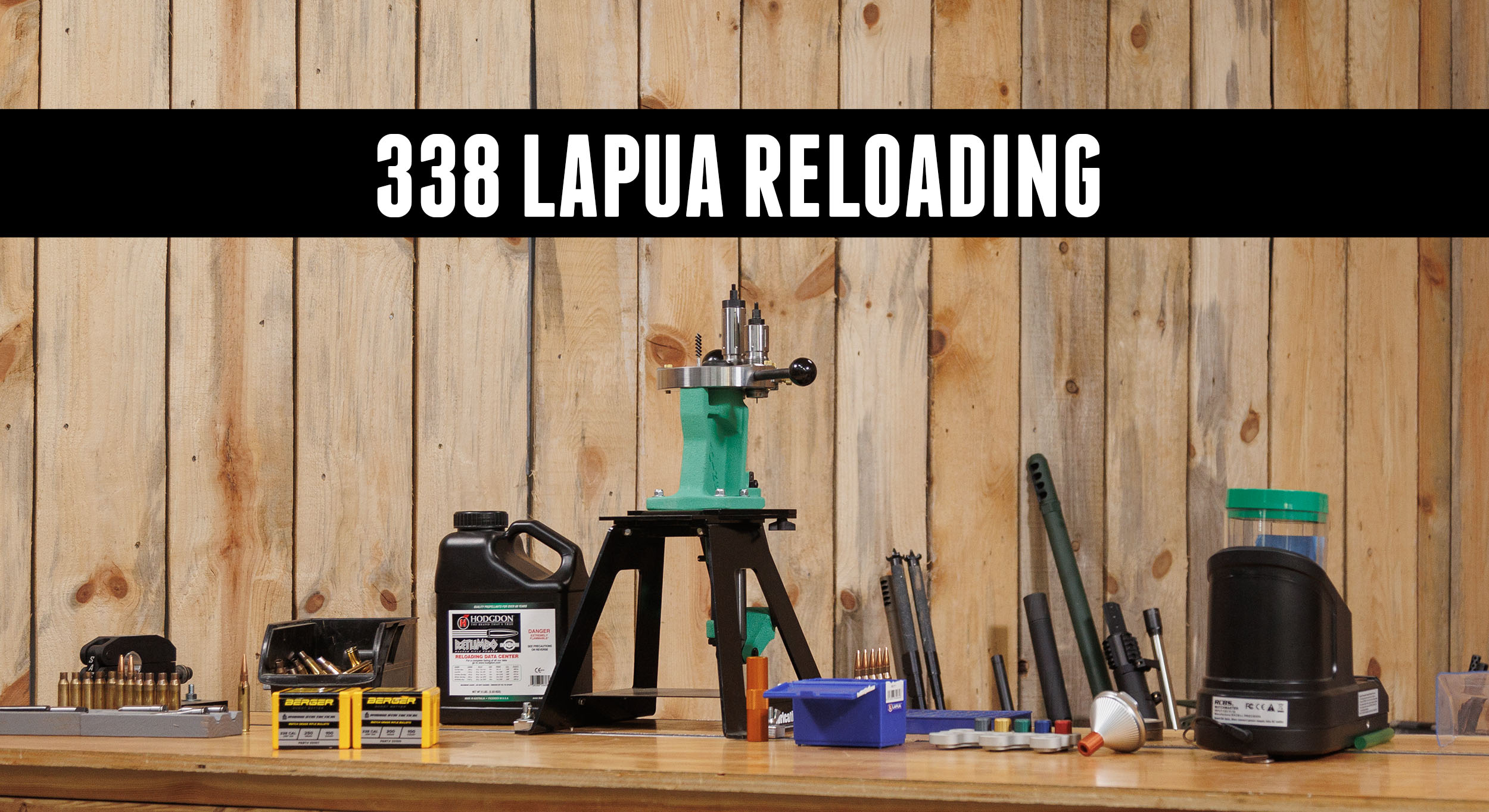
Loading Precision .338 with Triebel Dies
It’s incredibly rewarding to build a rifle, load the ammo for it, and shoot it to measure the results. I decided to take out the .338 Lapua Freedom Rifle and do some load development with it. Disclaimer Ultimate Reloader LLC / Making with Metal Disclaimer: (by reading this article and/or watching video content you accept […]
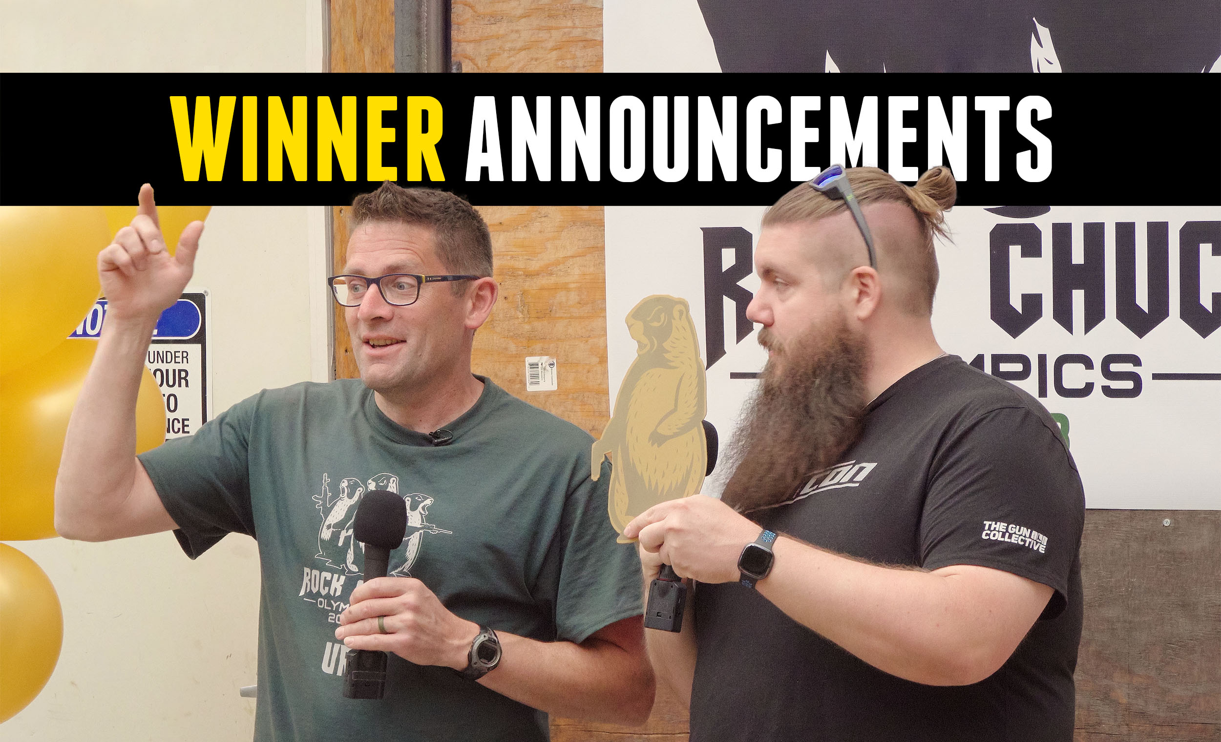
Rock Chuck Olympics E9: Winner and Awards Ceremony
With all shooting complete, it’s time to announce the winner of the 2023 Rock Chuck Olympics! Disclaimer Ultimate Reloader LLC / Making with Metal Disclaimer: (by reading this article and/or watching video content you accept these terms). The content on this website (including videos, articles, ammunition reloading data, technical articles, gunsmithing and other information) is […]
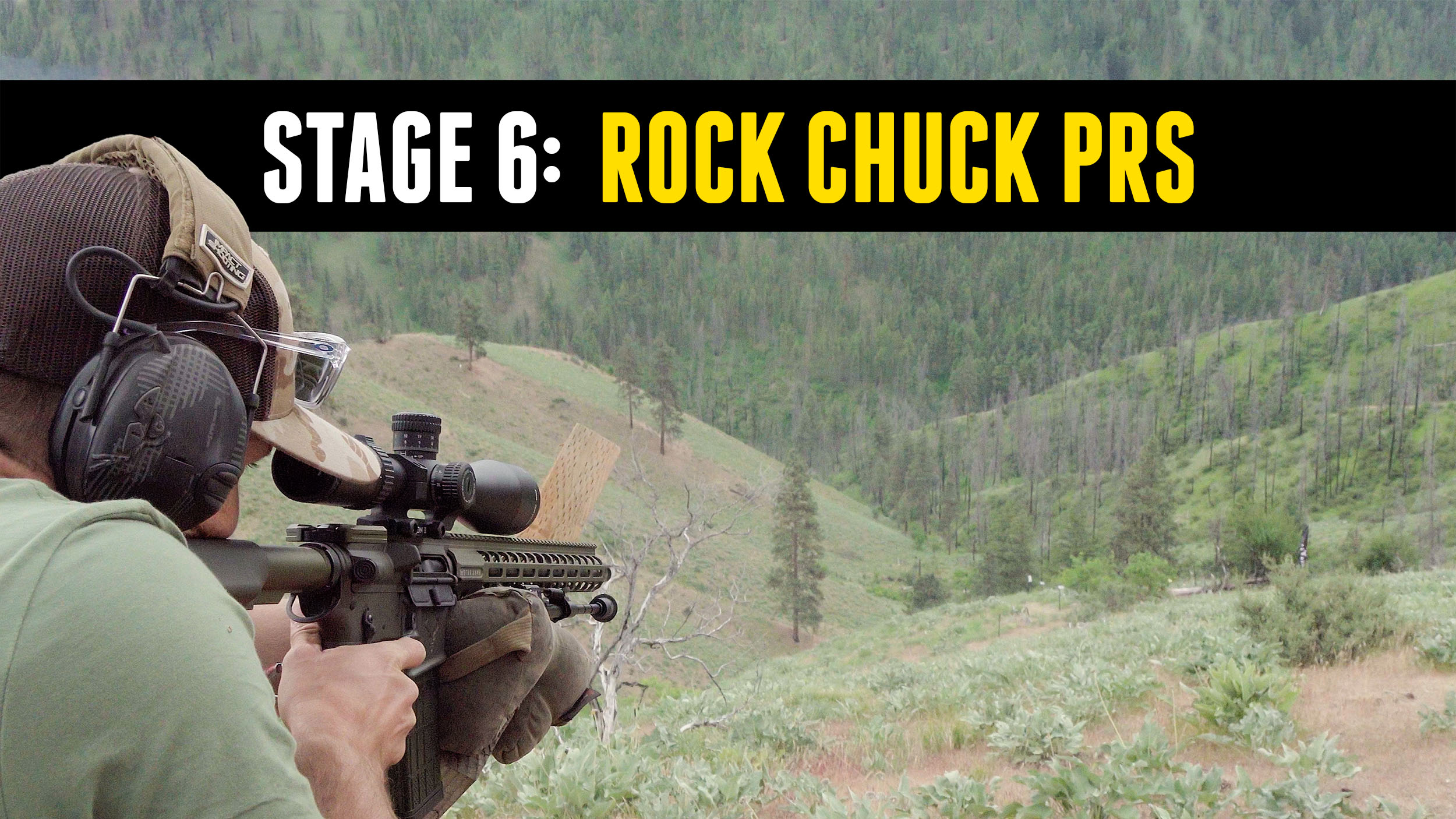
Rock Chuck Olympics E8: Rock Chuck PRS
Several of our competitors have considerable experience in PRS including Piet Malan and Erik Cortina. This final stage of the Rock Chuck Olympics gave them their best shots at the title. Disclaimer Ultimate Reloader LLC / Making with Metal Disclaimer: (by reading this article and/or watching video content you accept these terms). The content on […]
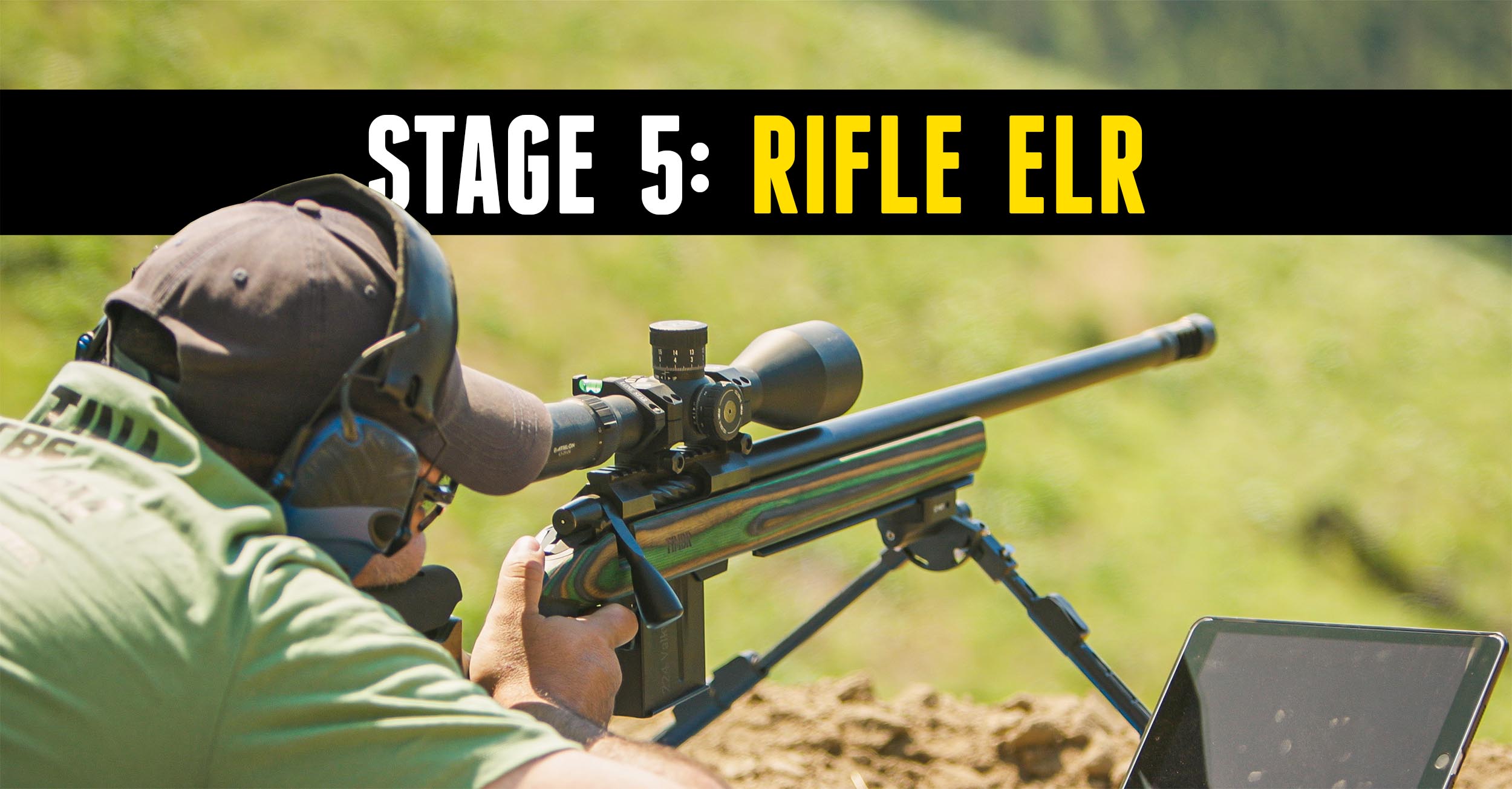
2023 Rock Chuck Olympics Episode 7: Rifle ELR
After taking the Canik Rival-S long distance, it was time for our RCO competitors to take on Harold the evil rock chuck during our rifle ELR stage. Disclaimer Ultimate Reloader LLC / Making with Metal Disclaimer: (by reading this article and/or watching video content you accept these terms). The content on this website (including videos, […]
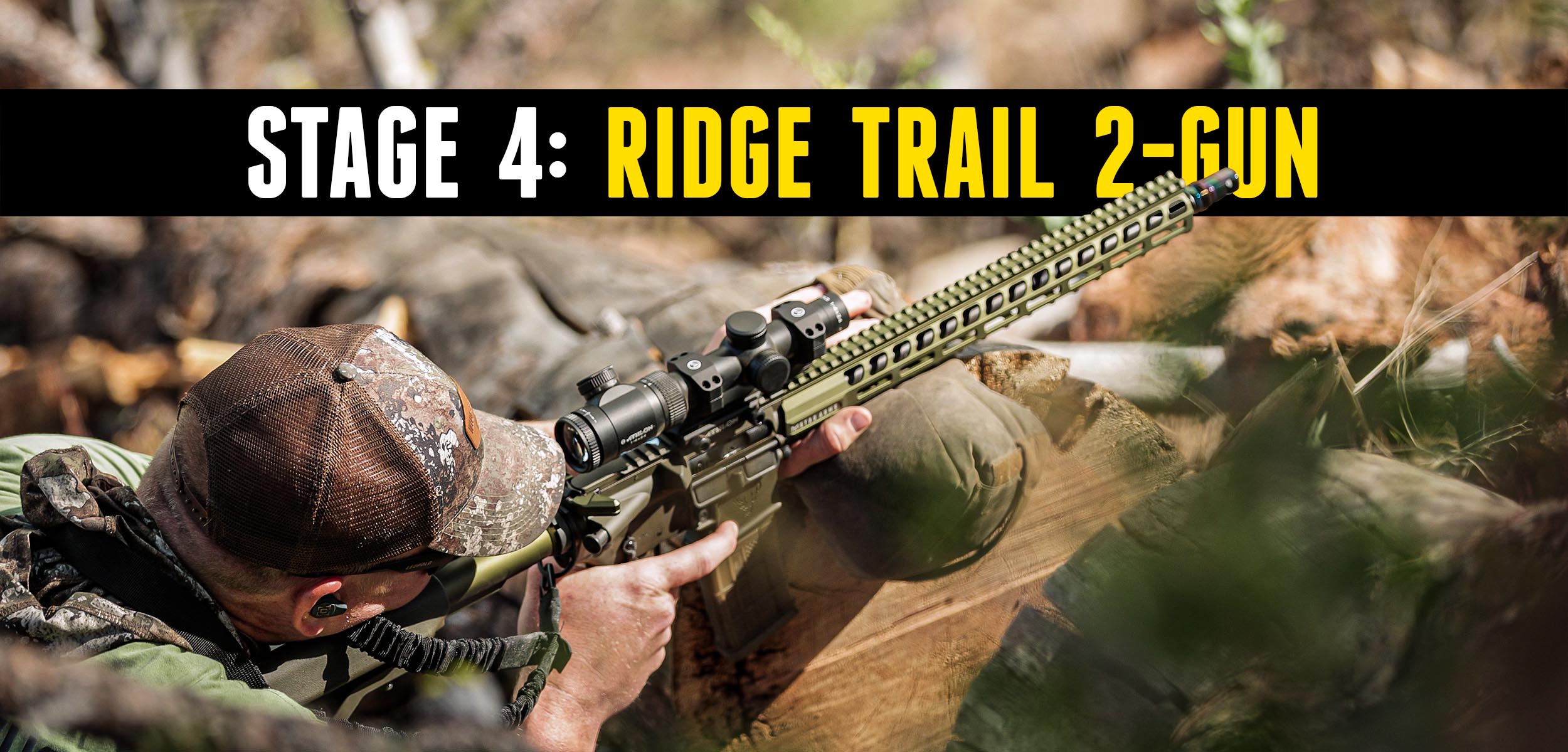
2023 Rock Chuck Olympics Episode 6: Ridge Trail 2-Gun
The Ridge Trail 2-Gun stage proved to be one of the most challenging stages yet. As it involved switching between carbines and pistols over tough terrain, it really mixed up the standings. Watch to see what happened! Disclaimer Ultimate Reloader LLC / Making with Metal Disclaimer: (by reading this article and/or watching video content you […]
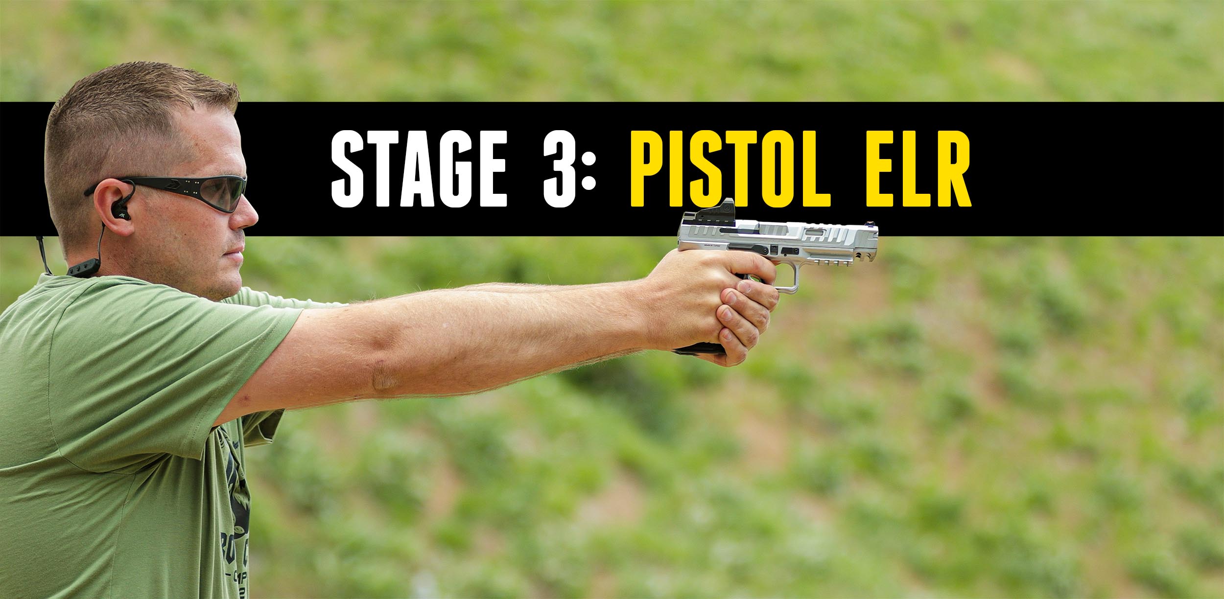
2023 Rock Chuck Olympics Episode 5: Pistol ELR
Stage 3, Pistol ELR, was designed to be challenging for everyone. You hear about long pistol shots, but most have never attempted them. This stage put competitors on the spot. Disclaimer Ultimate Reloader LLC / Making with Metal Disclaimer: (by reading this article and/or watching video content you accept these terms). The content on this […]
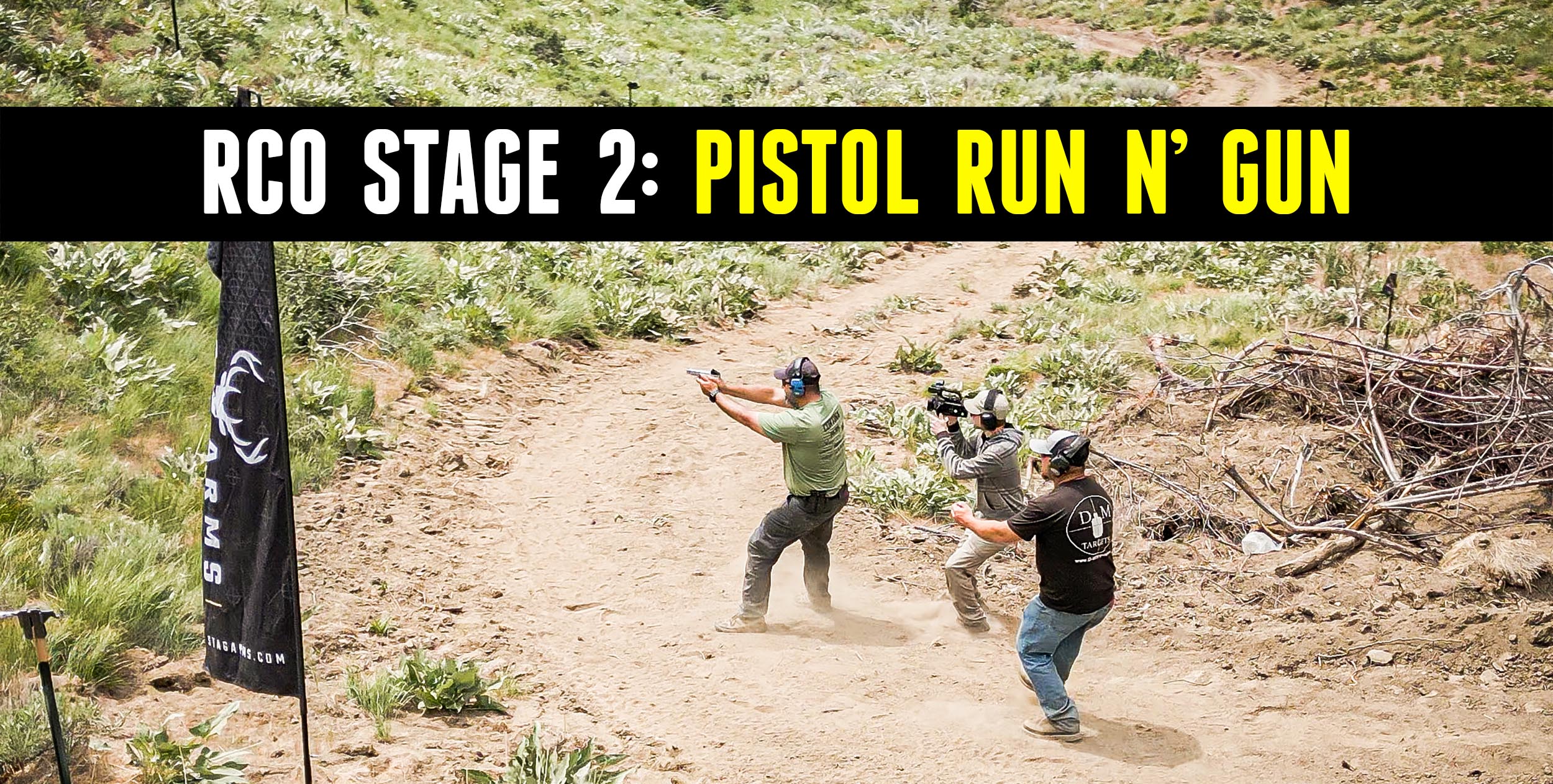
Rock Chuck Olympics E4: Pistol Run-N-Gun
Stage two, Pistol Run N’ Gun depended largely on speed and was aimed at world champion Nils Jonasson. Disclaimer Ultimate Reloader LLC / Making with Metal Disclaimer: (by reading this article and/or watching video content you accept these terms). The content on this website (including videos, articles, ammunition reloading data, technical articles, gunsmithing and other […]
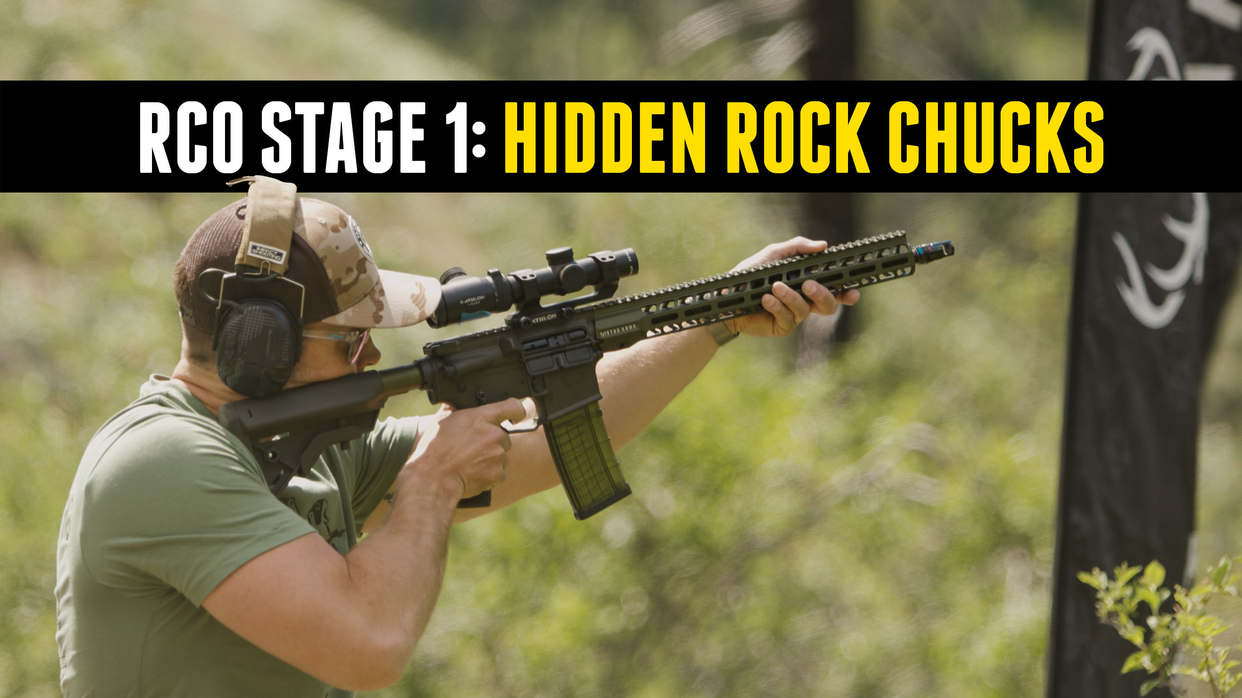
2023 Rock Chuck Olympics Episode 3: Hidden Rock Chucks
Each stage of the Rock Chuck Olympics was designed to be fun and challenging, but also cater to the strengths of one or more of the competitors. Stage one, Hidden Rock Chucks, was designed with our hunters in mind, Who-Tee-Who and Backfire. Disclaimer Ultimate Reloader LLC / Making with Metal Disclaimer: (by reading this article […]
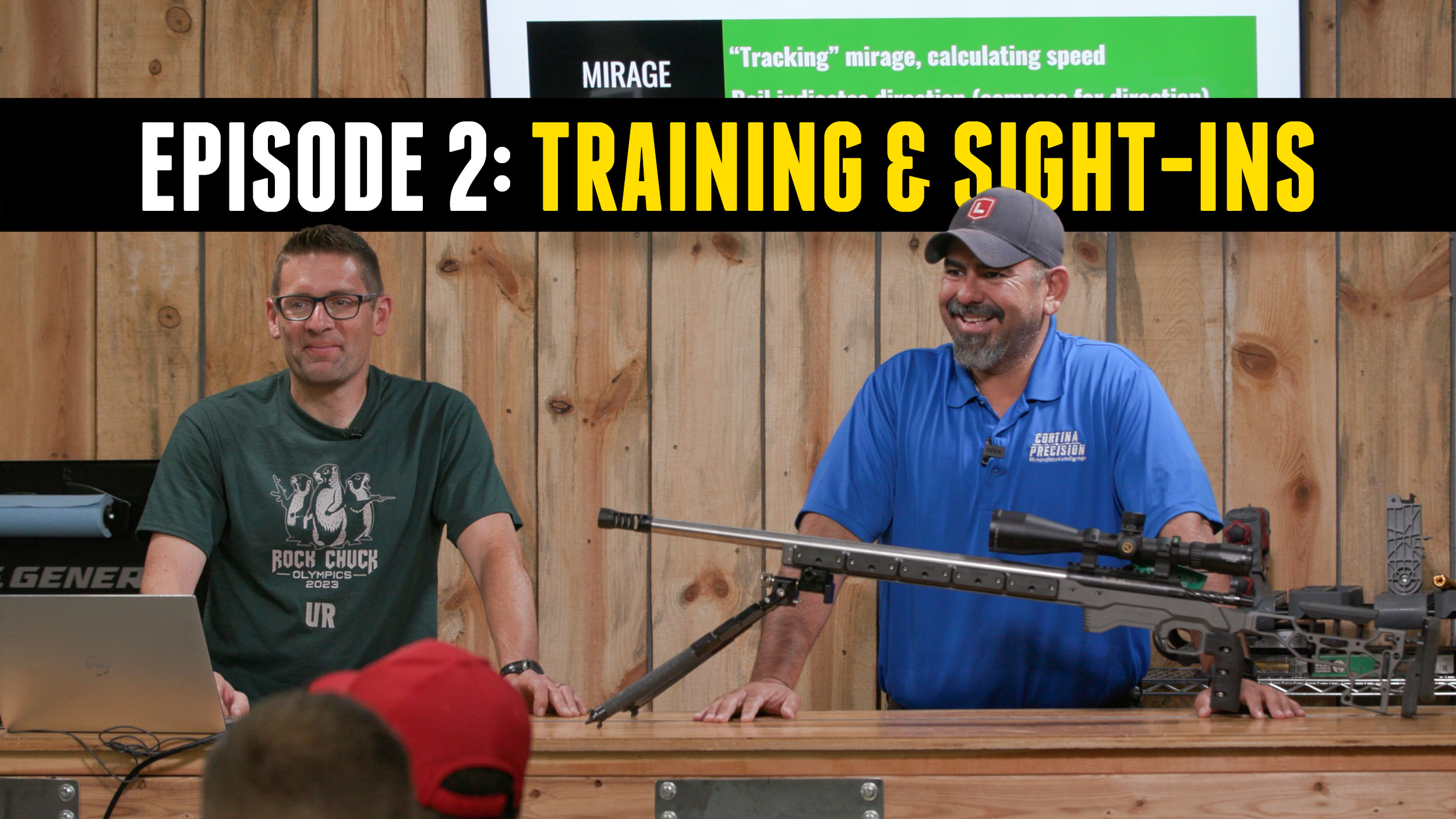
2023 Rock Chuck Olympics E2: Training & Sight In
Day one of the Rock Chuck Olympics began with training and sight-in as each competitor readied themselves for the competition. Disclaimer Ultimate Reloader LLC / Making with Metal Disclaimer: (by reading this article and/or watching video content you accept these terms). The content on this website (including videos, articles, ammunition reloading data, technical articles, gunsmithing […]
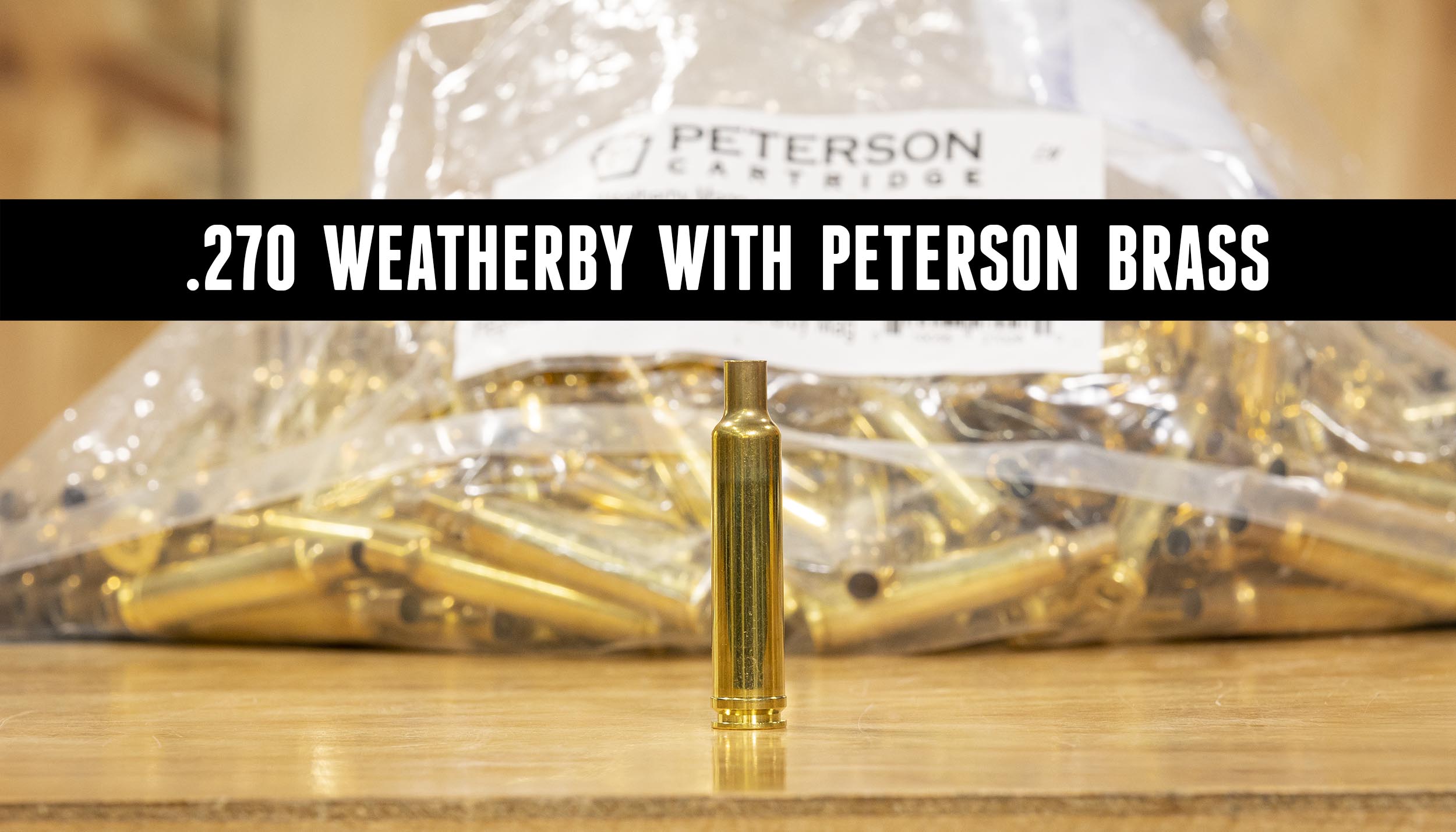
270 Weatherby -vs- Steel Target!
When I was a kid, my friend Chris’s dad had a Weatherby Mark V he got from opening a bank account. To this day, I still remember how beautiful it was. The ammo came in a box decorated with a safari theme and I believe it was a .300 Weatherby magnum. Forty years later, I […]
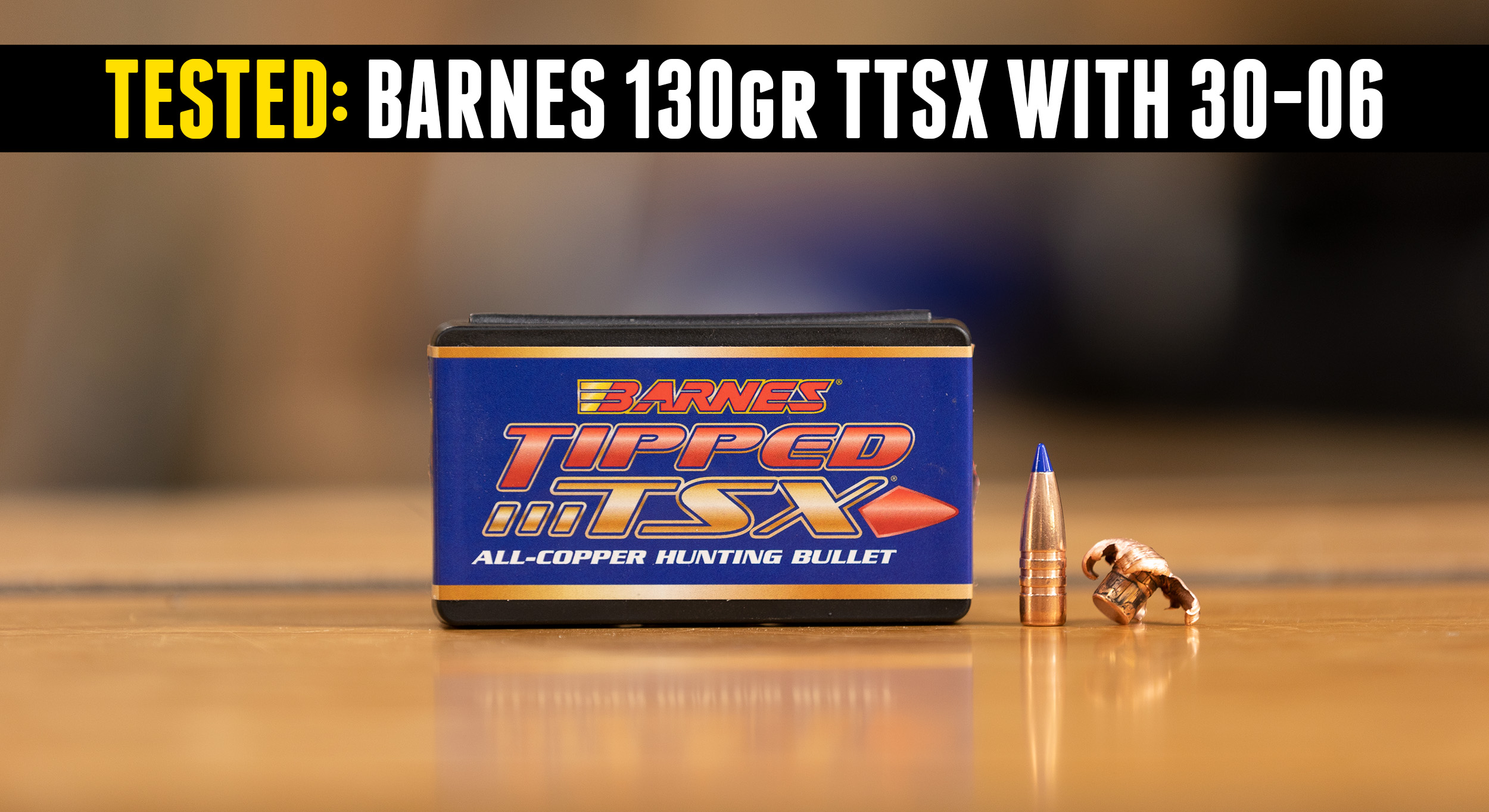
TESTED: Barnes 130 grain 30 Caliber TTSX Bullets
A 130 grain hunting bullet in .30 caliber? Yes, these bullets are screamers and accurate as well! Another well-regarded hunting bullet from our friends at Barnes Bullets. Disclaimer Ultimate Reloader LLC / Making with Metal Disclaimer: (by reading this article and/or watching video content you accept these terms). The content on this website (including videos, […]
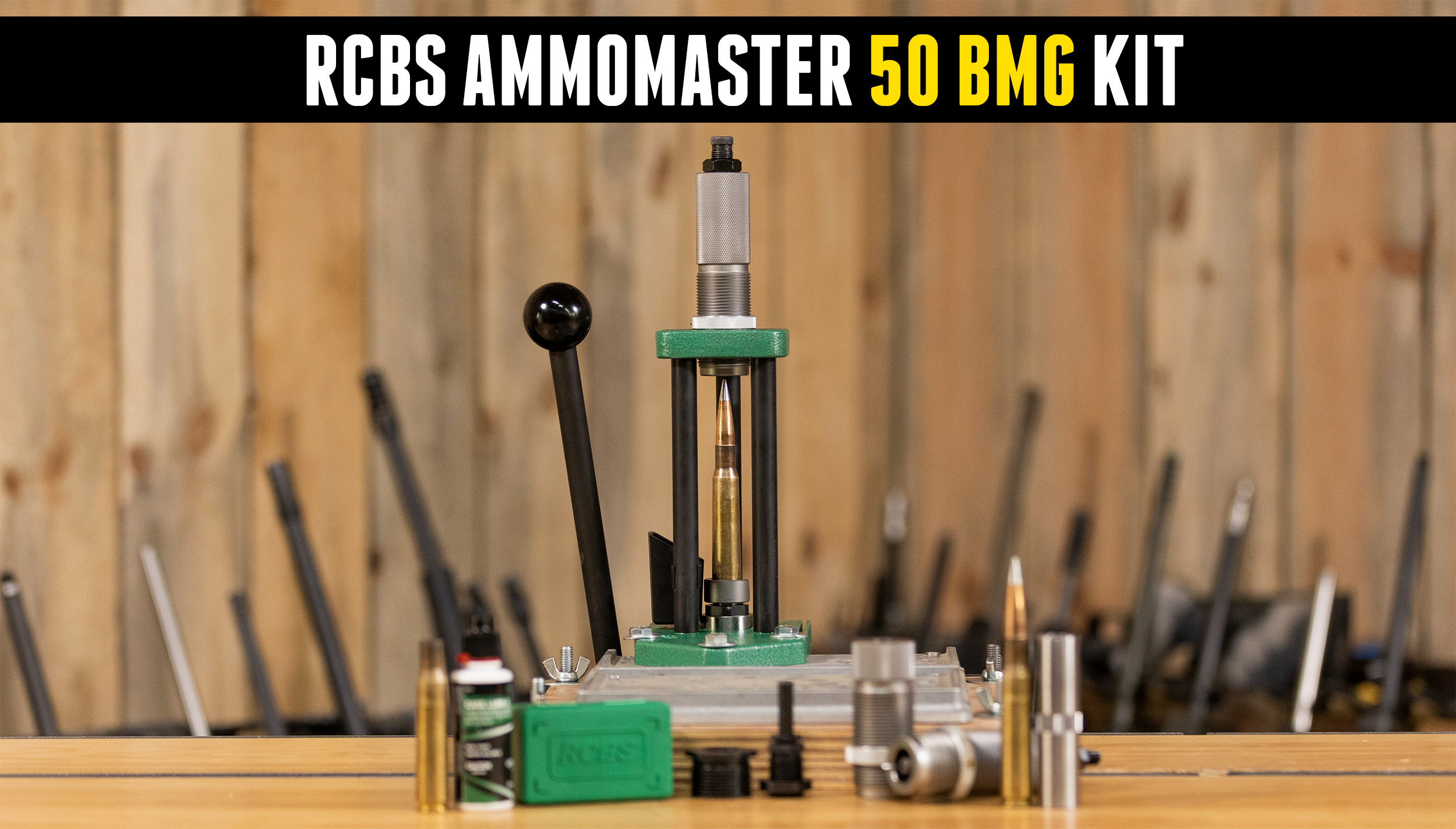
RCBS Ammomaster 50 BMG Pack (Unboxing and Quick Demo)
With my 50 BMG “Incredible Hulk” build complete, it’s time to get ready load ammunition! This time, we’re getting ready to use the RCBS Ammomaster 50 BMG Pack. Disclaimer Ultimate Reloader LLC / Making with Metal Disclaimer: (by reading this article and/or watching video content you accept these terms). The content on this website (including […]
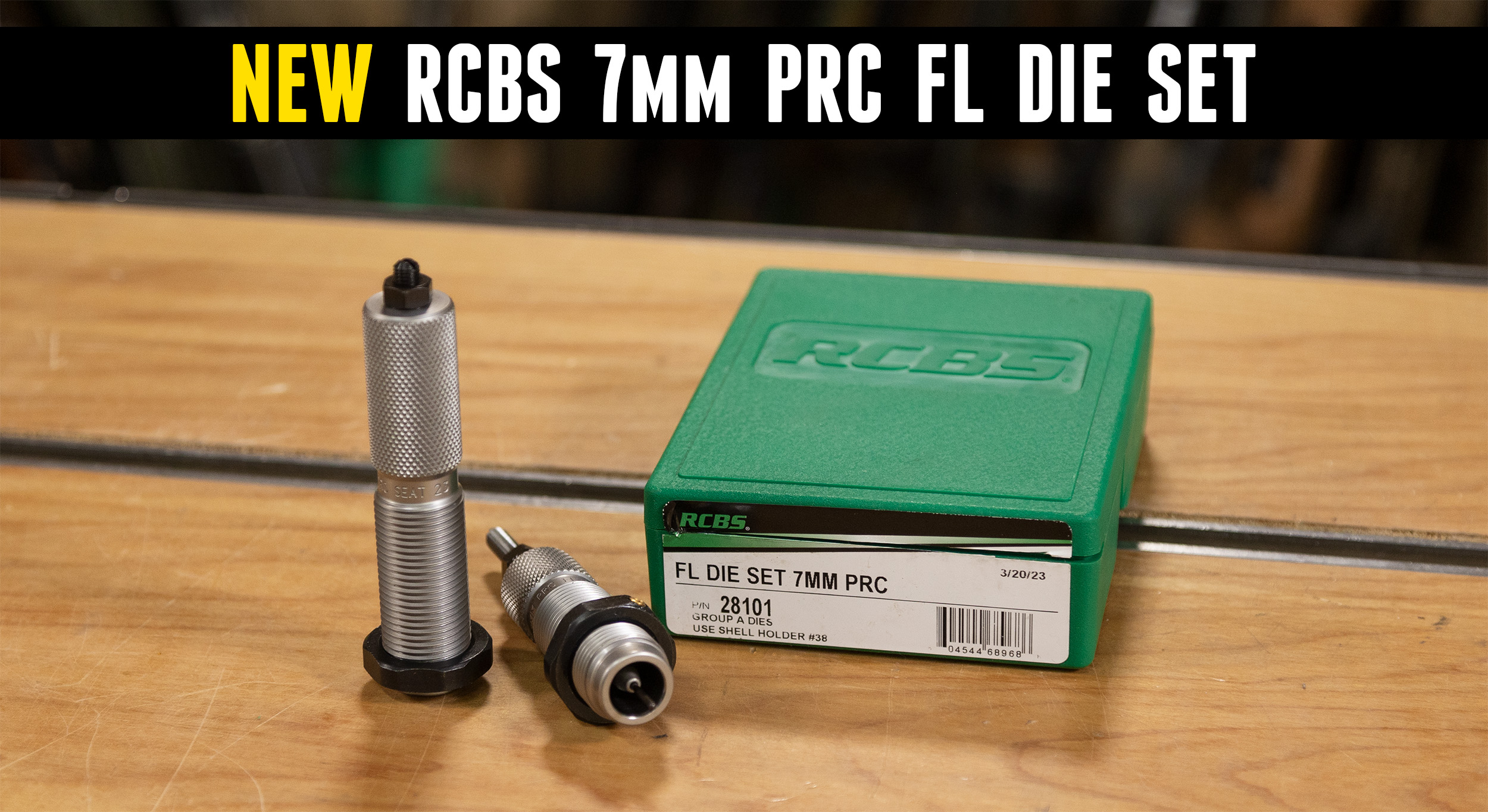
Quick Look: RCBS 7mm PRC Dies
7mm PRC has taken the gun world by storm. We were fortunate enough to be part of Hornady’s official launch, creating two custom builds, our Freedom rifle and Bergara full-custom. We’ve also compared the cartridge to 6.5 PRC, 300 PRC and 7mm Rem Mag. Disclaimer Ultimate Reloader LLC / Making with Metal Disclaimer: (by […]
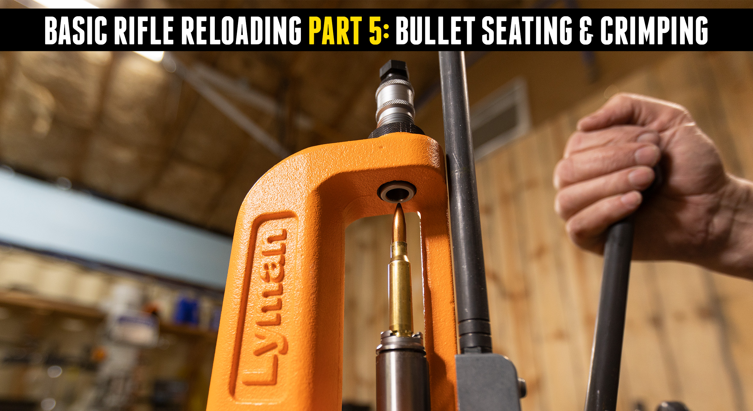
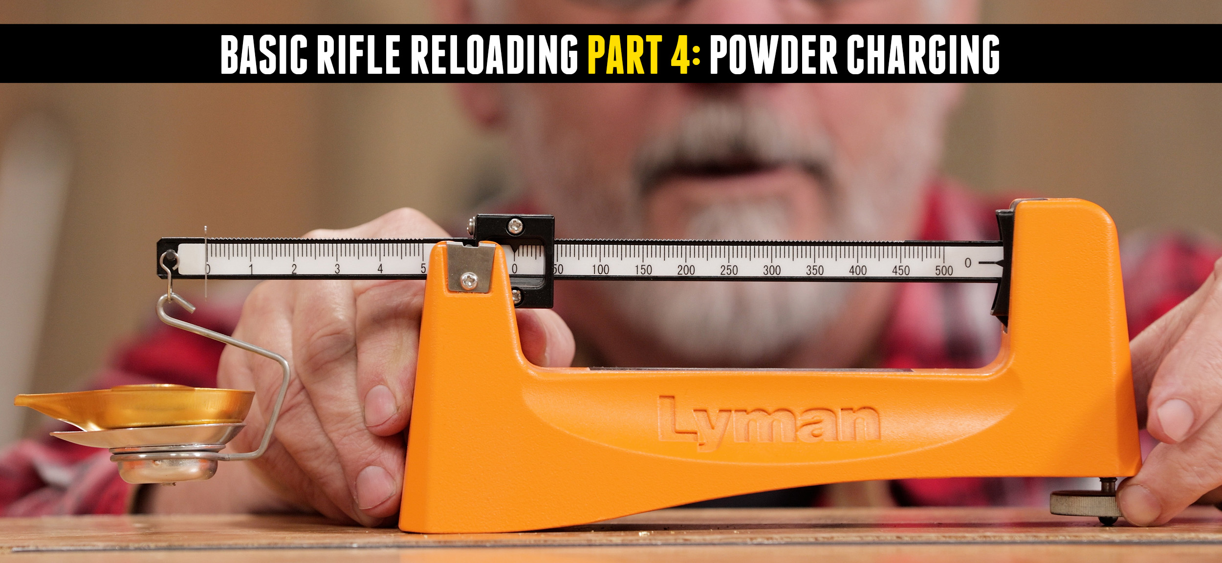
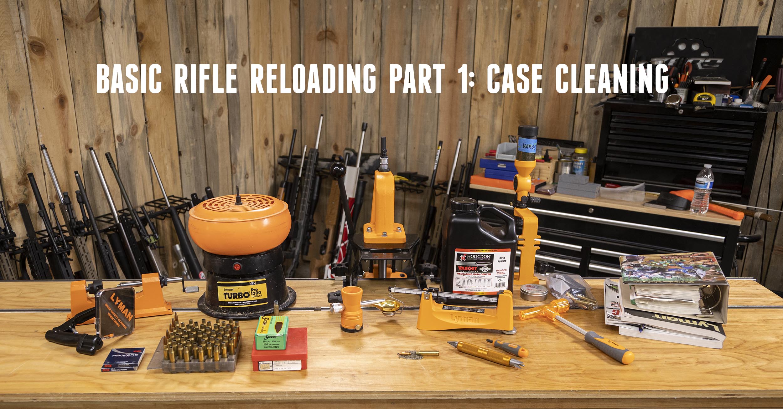
Basic Rifle Reloading 5: Bullet Seating & Crimping
At this point we have cleaned and lubed the brass, resized it, primed it and dropped in the powder charge. It’s time to seat the bullet! Disclaimer Ultimate Reloader LLC / Making with Metal Disclaimer: (by reading this article and/or watching video content you accept these terms). The content on this website (including videos, articles, […]
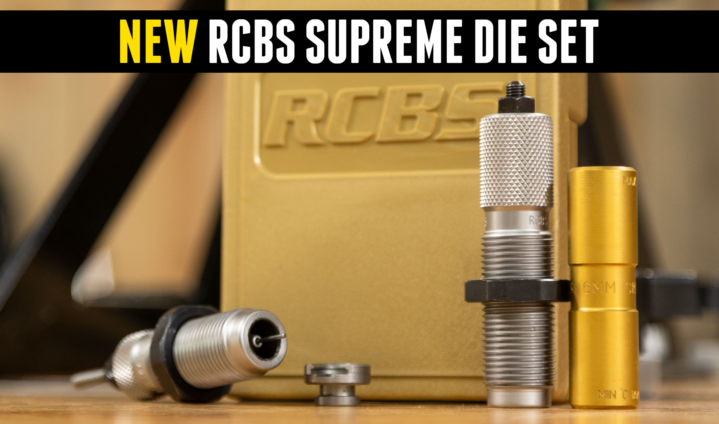
TESTED: RCBS Supreme Die Set
At SHOT Show 2023 we introduced you to the new RCBS Supreme Dies. This time, we have them in hand! Disclaimer Ultimate Reloader LLC / Making with Metal Disclaimer: (by reading this article and/or watching video content you accept these terms). The content on this website (including videos, articles, ammunition reloading data, technical articles, gunsmithing […]

Success: Hornady 178gr ELD-X on Elk at 405 yards (30-06)
We’ve tested Hornady’s ELD-X hunting bullet in a number of different calibers and have been consistently impressed with its accuracy and performance in Clear Ballistics Gel blocks. It was time to take that bullet elk hunting! *Note: This is a successful hunting story and video. The harvest is shown here and in the video. Disclaimer […]
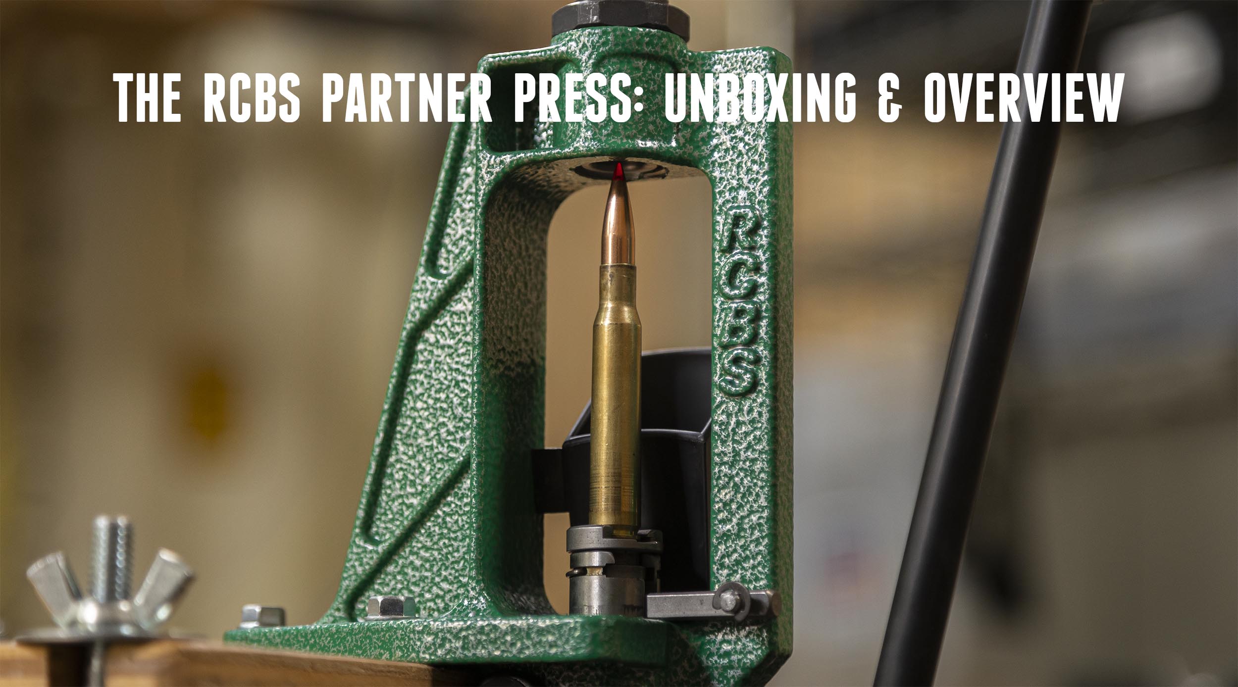
RCBS Lightweight Partner Press Unboxing and Overview
Sometimes less is more. Many presses are large, bulky, and very heavy. However, from time to time, a handloader may want a smaller, lighter press. The RCBS Partner Press is an interesting alternative to large, heavy presses. Disclaimer Ultimate Reloader LLC / Making with Metal Disclaimer: (by reading this article and/or watching video content you […]